Automatic analyzer

a technology of automatic analysis and analyzer, applied in the field of automatic analyzer, can solve problems such as increasing costs

Active Publication Date: 2006-07-06
HITACHI HIGH-TECH CORP
View PDF17 Cites 16 Cited by
  • Summary
  • Abstract
  • Description
  • Claims
  • Application Information

AI Technical Summary

Benefits of technology

[0015] According to the present invention, it is possible to confirm the state of the automatic analyzer from a distance.

Problems solved by technology

However, if any abnormality occurs in the system, the technique disclosed in Patent Document 1 cannot inform the abnormality by using the display screen.
Also, an indicator lamp may be added to display the occurrence of an abnormality in the automatic analyzer, but this solution increases the cost.

Method used


Image

  • Automatic analyzer
  • Automatic analyzer
  • Automatic analyzer

Examples


Embodiment Construction

[0021]FIG. 5 schematically shows a basic arrangement of an automatic analyzer. In FIG. 5, reference numeral 2-1 denotes a reaction disc. Reaction cuvettes 2-2 are placed on an outer peripheral portion of the reaction disc 2-1. The whole of the reaction disc 2-1 is held at a predetermined temperature by a reaction disc incubator 2-3.

[0022] Reference numeral 2-5 denotes a sample disc mechanism for holding samples. Many test tubes containing samples and having barcodes 2-6 affixed thereto are placed on the sample disc mechanism. The sample in each test tube affixed with the barcode 2-6 is extracted, as required, by a nozzle 2-8 of a sample pipetter 2-7, and is poured into the reaction cuvette 2-2 placed in a sample pipetting position. Reference numerals 2-9A1, 2-9B1 denote reagent disc mechanisms on which reagent bottles each affixed with a barcode label are placed. Barcode readers 2-27A, 2-27B are associated with the reagent disc mechanisms 2-9A1, 2-9B1, respectively. At the time of ...


PUM

PropertyMeasurementUnit
distanceaaaaaaaaaa
temperatureaaaaaaaaaa
timeaaaaaaaaaa

Abstract

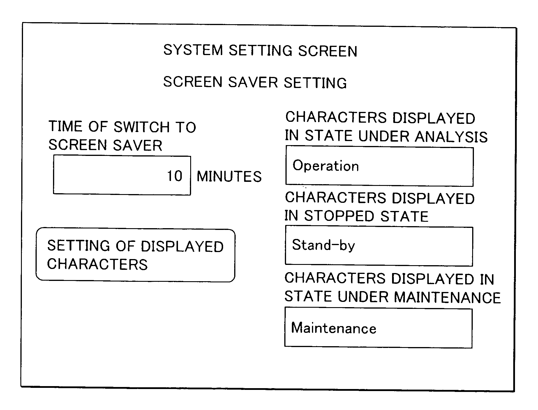
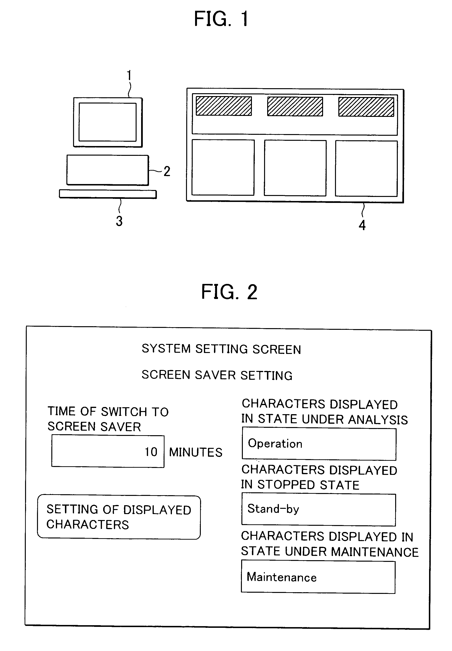
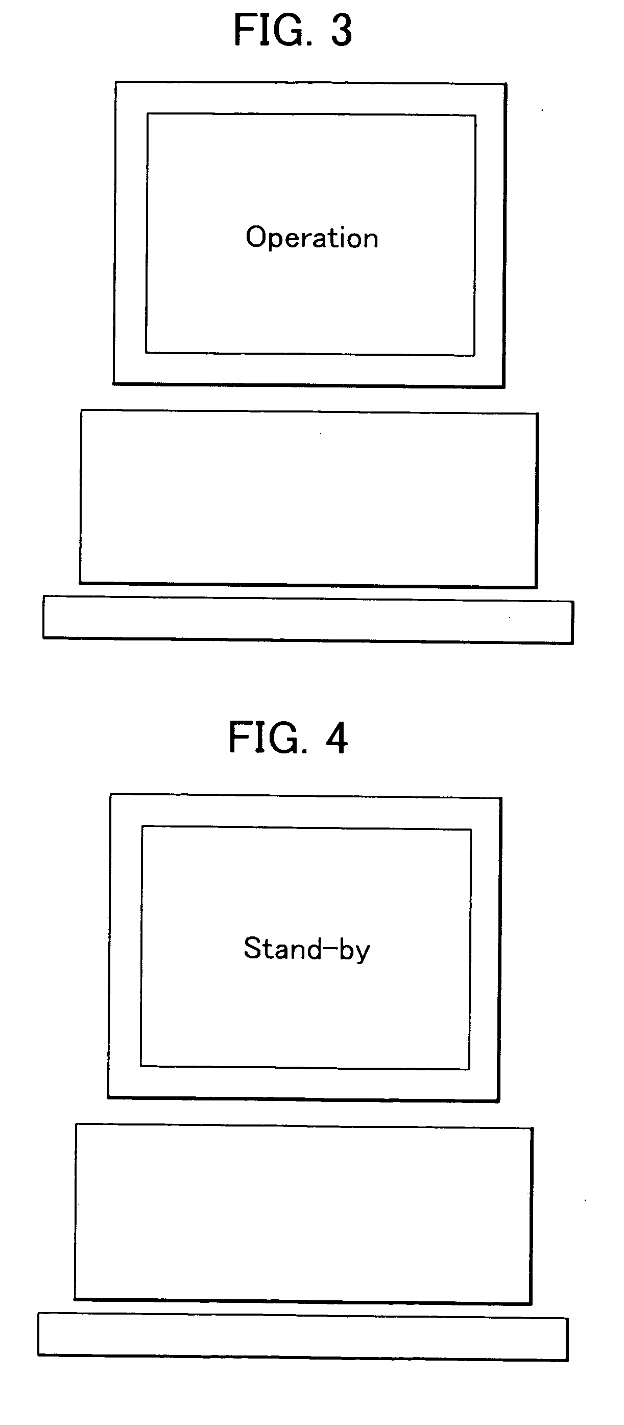
In an automatic analyzer for performing qualitative and quantitative analyses of living samples, such as blood and urine, a capability of recognizing the analyzer state, e.g., the state under run of analysis or the stopped state, from a distance is provided without increasing the cost. To realize that capability, the screen saver function of a display is modified to have the function of recognizing the analyzer state and reflecting the recognized analyzer state on a design of a screen image displayed with the screen saver function.

Description

BACKGROUND OF THE INVENTION [0001] 1. Field of the Invention [0002] The present invention relates to an automatic analyzer for performing qualitative and quantitative analyses of living samples, such as blood and urine. More particularly, the present invention relates to an automatic analyzer provided with a display for displaying an operating screen. [0003] 2. Description of the Related Art [0004] An automatic analyzer for analyzing the quantities of particular components in living samples, such as blood and urine, or detecting the presence of a particular antigen or antibody has been more increasingly employed primarily in large-scaled hospitals and test centers for the reasons that the automatic analyzer can more quickly perform measurements than manual operations and has higher reproducibility of the analysis results. In some of recent situations, a plurality of automatic analyzers are installed and operated by one clinic test operator for the purposes of increasing analysis eff...

Claims


Application Information

Patent Timeline
Patent Type & Authority Applications(United States)
IPC IPC(8): G09G3/16G01N35/00
CPCG01N35/00594G01N2035/00891
Inventor TANAKA, KAZUHIRO
Owner HITACHI HIGH-TECH CORP
Why Eureka
Try Eureka