Inkjet carriage unit, inkjet recording apparatus, and image forming apparatus

Inactive Publication Date: 2006-07-06
RICOH KK
View PDF8 Cites 22 Cited by
  • Summary
  • Abstract
  • Description
  • Claims
  • Application Information

AI Technical Summary

Benefits of technology

[0007] Accordingly, it is a general object of the present invention to provide

Problems solved by technology

This is because longer apparatus service life may cause contamination of the encoder sensor, specifically, its light emission part and light reception part, with ink mist, thus causing a p

Method used


Image

  • Inkjet carriage unit, inkjet recording apparatus, and image forming apparatus
  • Inkjet carriage unit, inkjet recording apparatus, and image forming apparatus
  • Inkjet carriage unit, inkjet recording apparatus, and image forming apparatus

Examples


Example

First Embodiment

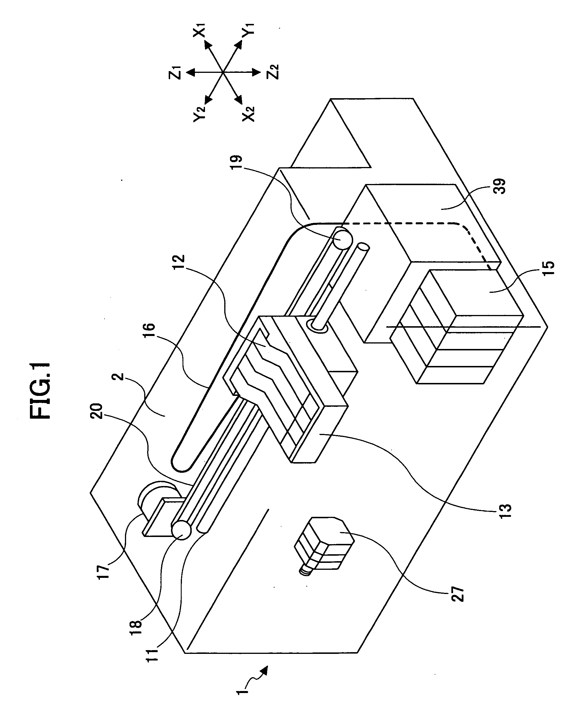
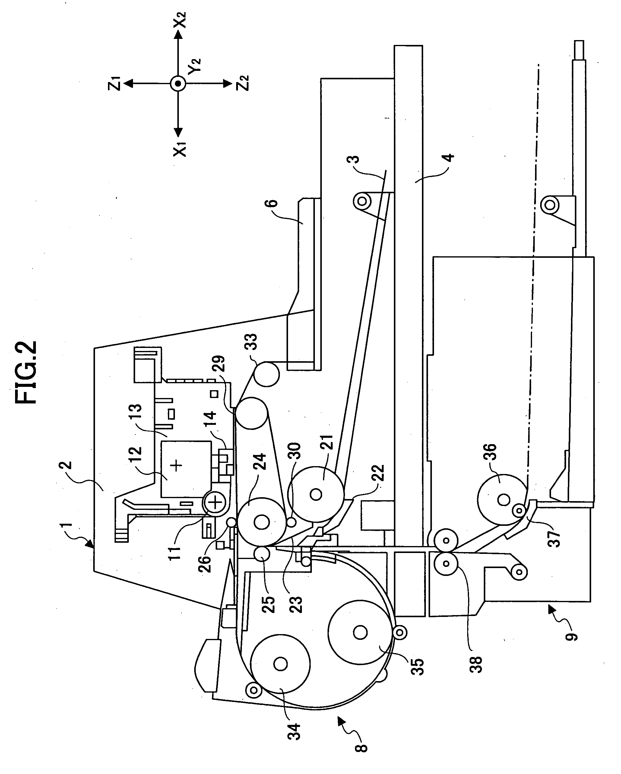
[0023]FIG. 1 is a perspective view of an inkjet recording apparatus, which is an example of the image forming apparatus to which the present invention is applied, according to a first embodiment of the present invention. FIG. 2 is a side view of a mechanism part of the inkjet recording apparatus of FIG. 1. The inkjet recording apparatus has a print mechanism part 2 housed in a main body 1 of the inkjet recording apparatus. The print mechanism part 2 includes a carriage 13, a recording head 14, and sub tanks (ink cartridges) 12. The carriage 13 is movable in the main scanning directions (Y1 and Y2 directions in FIGS. 1 and 2). The recording head 14 includes multiple inkjet heads mounted on the carriage 13. The sub tanks 12 supply ink to the recording head 14. A paper feed cassette 4 (or a paper feed tray) capable of carrying multiple sheets of paper 3 is attached detachably and reattachably to a lower part of the main body 1 from its front side (X1 side). The paper 3...

Example

Second Embodiment

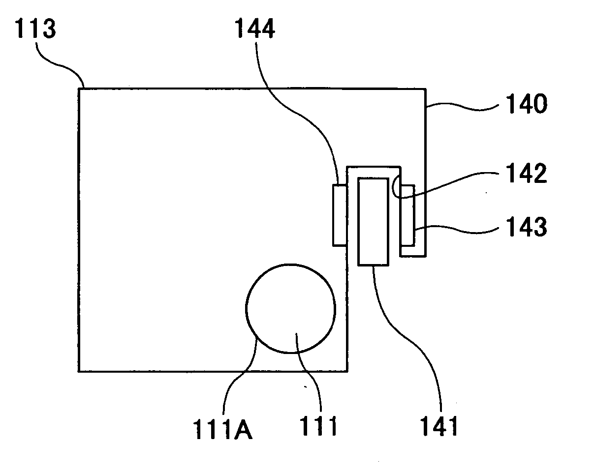
[0035] Further, in the first embodiment, the sensor holding member 50 is detachable from and reattachable to the main body 13a of the carriage 13 in the vertical directions. Alternatively, as shown in FIG. 7, a sensor holding member 50A may be formed like a flange so as to be fixable to a side of the carriage 13 with a screw, and be attached and detached laterally. Further, if the positional relationship with the main guide rod 11 allows in terms of structure, the sensor holding member 50 may be attached and detached from the lower (Z2) side or the rear (X2) side of the carriage 13. Any structure may be employed as long as the structure allows the sensor holding member 50 to be attached and detached with the carriage 13 being attached to the main guide rod 11.

[0036] Thus, according to one aspect of the present invention, a carriage and an encoder sensor can be replaced without removing a linear scale. As a result, an operator is less likely to touch the linear sca...


PUM


Abstract

An inkjet carriage unit is disclosed that includes a main body, a sensor holding part detachably attached to the main body, and an encoder sensor attached to the sensor holding part.

Description

BACKGROUND OF THE INVENTION [0001] 1. Field of the Invention [0002] The present invention relates generally to an inkjet carriage unit and an image forming apparatus, such as an inkjet recording apparatus, using the same. [0003] 2. Description of the Related Art [0004] Image forming apparatuses such as inkjet recording apparatuses have a scanning part that causes a carriage having recording heads mounted thereon to scan paper in a predetermined scanning direction while guiding the carriage with a guide rod. The recording heads are driven based on image data during scanning by the carriage so that an image is formed. In general, these inkjet recording apparatuses includes a linear scale bearing marks for detecting the position of printing heads, and a read sensor to read the marks while moving along the linear scale. The linear scale is shaped like an elongated film extending in the scanning direction of the carriage. Its marks are provided at very narrow intervals (for example, 0.08...

Claims


Application Information

Patent Timeline
IPC IPC(8): B41J2/175
CPCB41J19/207
Inventor NARUSE, SHINICHIRO
Owner RICOH KK
Why Eureka
Try Eureka