Apparatus for radar

Inactive Publication Date: 2006-06-20
SAAB AB
View PDF13 Cites 18 Cited by
  • Summary
  • Abstract
  • Description
  • Claims
  • Application Information

AI Technical Summary

Benefits of technology

[0014]By means of what is proposed above, the problem mentioned by way of introduction can be given a relatively simple solution from a technical point of view. So-called non-parametric detection can be utilized. The combination with coherent clutter suppression is new and the use in combination with fully coherent radar has exceptional advantages. The invention can also eliminate disadva

Problems solved by technology

The measurement of range hereby becomes ambiguous, which is normally not desirable of the radar.
By means of such methods, suppression of slowly moving targets can also be achieved with a magnetron radar, but normally only for echoes within the radar's unambiguous range, due to the fact that first-time-around echoes and second-time-around echoes cannot be distinguished.
This means that the number of independent measurements during a radar pass is limited and thereby the opportunities to utilize the duration of an indication rather than amplitude as a measurement of occurrence are reduced.
This is a method that is difficult to use for transmitter elements that have frequency change characteristics that depend greatly upon the current power factor of the transmitter.
For such stations, a pulse length change can, it is true, be introduced at the same time as PRI variation in order to retain the power factor, but such a method can seldom be justified economically for, for example, a magnetron radar.
This method suffers from the same problem with varying power factor as the previous method.
In addition, the sensitivity o

Method used


Image

  • Apparatus for radar
  • Apparatus for radar
  • Apparatus for radar

Examples


Example

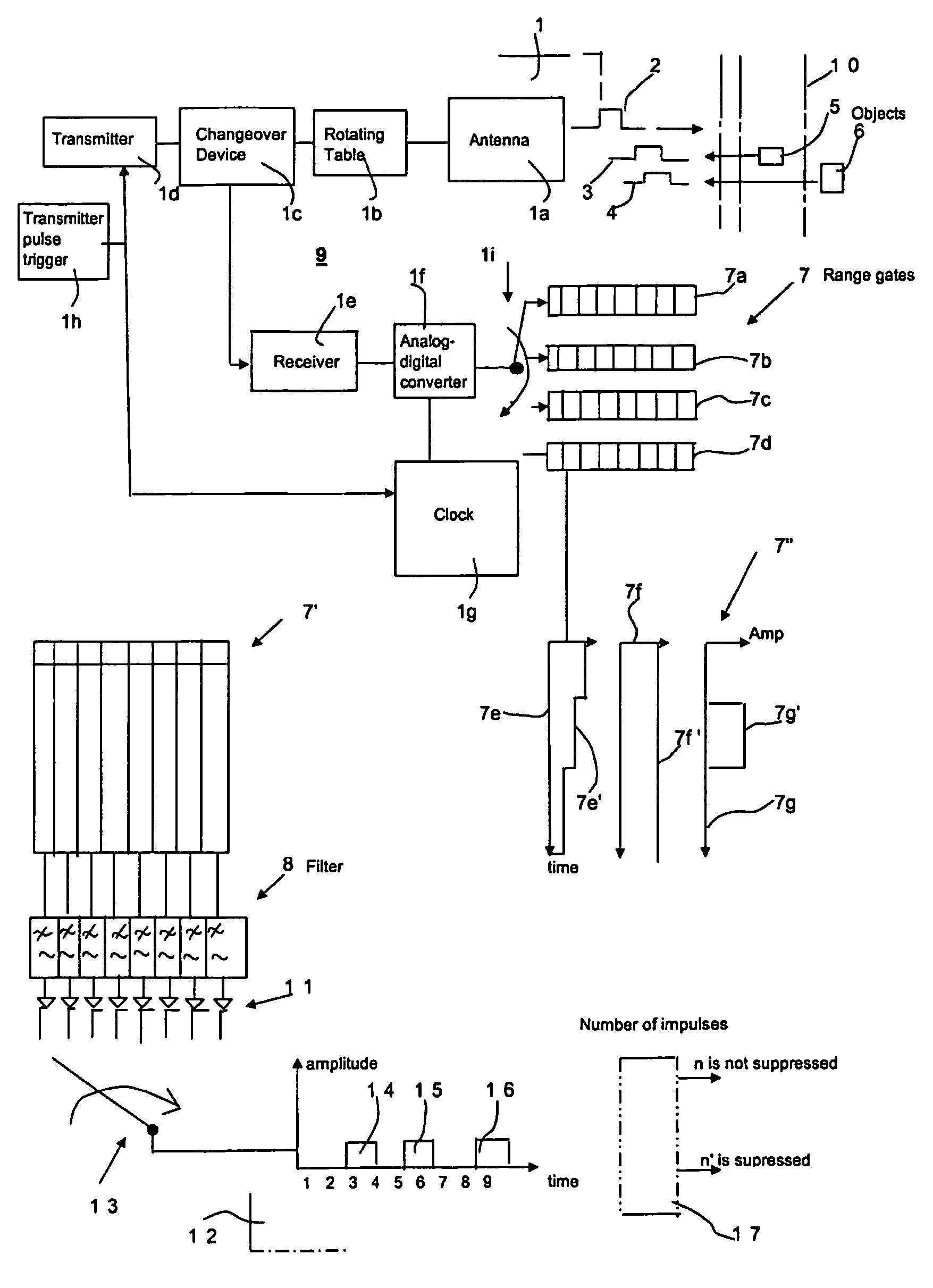
[0018]FIG. 1 shows a radar illustrated symbolically by 1. The radar is arranged to transmit electromagnetic energy or pulses 2 in pulse repetition intervals PRI and to receive reflections or echoes 3, 4 from objects 5, 6 that reflect the electromagnetic energy. The radar is arranged with range gates that are indicated in outline by 7, 7′, 7″. The respective range gates are provided with or interact with a Doppler filter or high pass filter 8. The radar works with a frequency that varies in accordance with a staggered or wobbling pattern. The functions achieved by the radar 1 are symbolized in outline by 9. The radar comprises an antenna 1a that is arranged to be able to rotate, with a rotating table 1b. A changeover device 1c connects the rotation table / antenna in turn to a transmitter 1d and a receiver 1e. The receiver 1e is connected to an analog-digital converter 1f. A clock is indicated by 1g and controls the transmitter and receiver circuits with a frequency related to the tran...


PUM


Abstract

A radar transmits electromagnetic energy in pulse repetition intervals and receives reflections from objects in range gates including Doppler filters. The radar approves desirable ambiguous echoes and suppresses ambiguous echoes of no interest or that interfere with the radar's display. The radar frequency varies according to a staggered or wobbling pattern. The ambiguous echoes produce one pulse in the range gates within a predetermined number of periods. The Doppler filter works with an impulse function response that includes a small number of samples. The Doppler filter, during the predetermined number of periods, gives rise to independent samples from reflectors within the radar's unambiguous range. When the independent samples exceed the small number of samples, the radar approves the ambiguous echo. Otherwise, it is suppressed. In this way, ambiguous echoes are prevented from interfering with the reception or display of echoes. The suppression of asynchronous interferences can be made easier.

Description

FIELD OF THE INVENTION[0001]The present invention relates to an apparatus for radar that is arranged to transmit electromagnetic energy in the form of pulses with given or predetermined intervals and to receive reflections or echoes from objects that reflect the electromagnetic energy. The radar works with time intervals with a fixed delay relative to the transmitted pulse and range gates in which the echoes are received. The time delay between successive received pulses will vary from pulse to pulse with a radially moving target which can be transferred, using known Doppler radar technology, to a varying phase position relative to a stable reference oscillator. By passing the signals through a high pass filter, non-moving echoes can be suppressed, so-called MTI technology. In addition, the radar is to approve ambiguous echoes that are desirable and to suppress ambiguous echoes that are of no interest or that interfere with the display function of the radar.BACKGROUND OF THE INVENTI...

Claims


Application Information

Patent Timeline
IPC IPC(8): G01S13/20G01S13/522G01S7/292G01S13/18G01S13/22
CPCG01S13/22G01S13/20G01S7/2923G01S13/18
Inventor BERGKVIST, BENGT
Owner SAAB AB
Why Eureka
Try Eureka