Code division multiplexing communication system

Inactive Publication Date: 2006-07-06
OKI ELECTRIC IND CO LTD
View PDF3 Cites 0 Cited by
  • Summary
  • Abstract
  • Description
  • Claims
  • Application Information

AI Technical Summary

Benefits of technology

[0011] An object of the present invention is to provide a code division multiplexing communication system with high bandwidth efficiency in low price, without decreasing the level of security.

Problems solved by technology

Therefore, in such conventional communication system, there often exist a band which is not in use and so bandwidth efficiency is low.
However, in case that a single channel is shared by a plurality of receivers, the above described security cannot be maintained as a single spread code may be shared by the plurality of receivers.

Method used


Image

  • Code division multiplexing communication system
  • Code division multiplexing communication system
  • Code division multiplexing communication system

Examples


Embodiment Construction

[0025] Embodiments of the present invention will be described below with reference to the drawings. In the drawings, sizes, shapes or placements of each element are schematically shown so as to make the invention understandable. Further, the numerical conditions explained below are only shown as examples.

[0026] An embodiment of the present invention will be explained with reference to the drawings. It is noted that, in the drawings, sizes, shapes or placements of each element are schematically shown so as to make the invention understandable. Further, the numerical conditions explained below are only shown as examples.

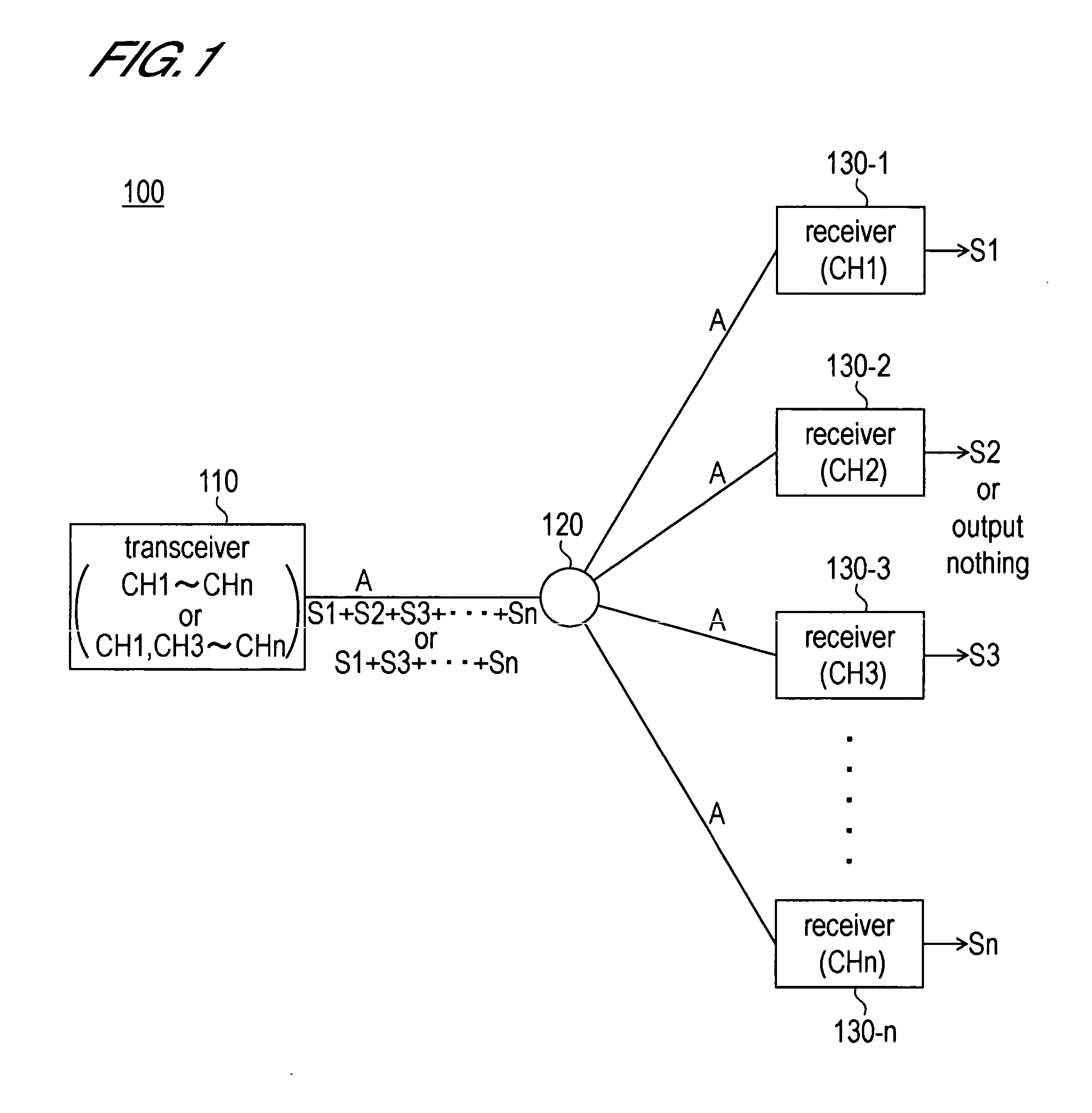
[0027]FIG. 1 is a conceptual view showing an entire structure of a communication system according to the present embodiment.

[0028] As shown in FIG. 1, a communication system 100 of the present invention includes a transceiver 110, a distributor 120, and a plurality of receivers 130-1 to 130-n.

[0029] The transceiver 110 performs code division multiplexing of signal ...


PUM


Abstract

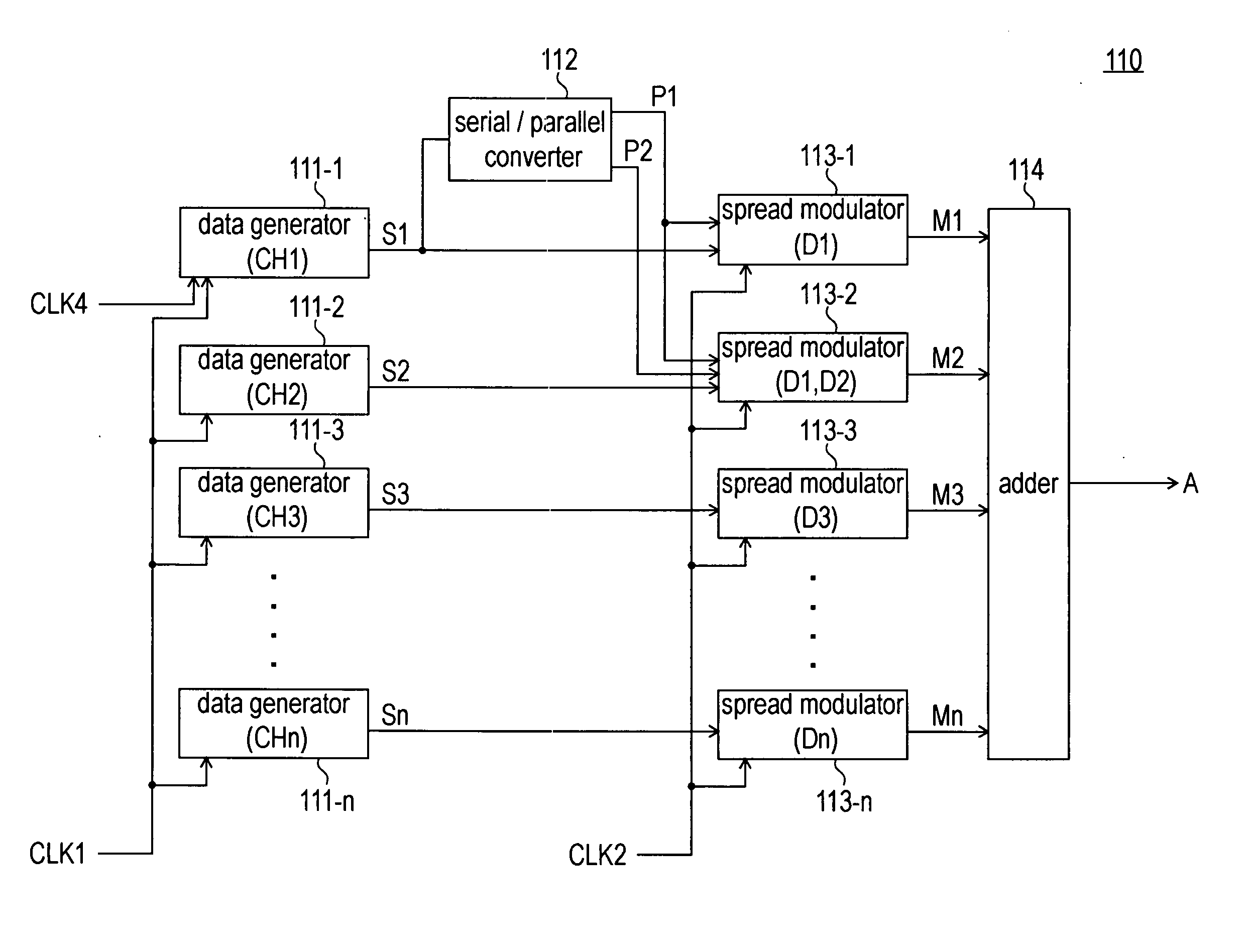
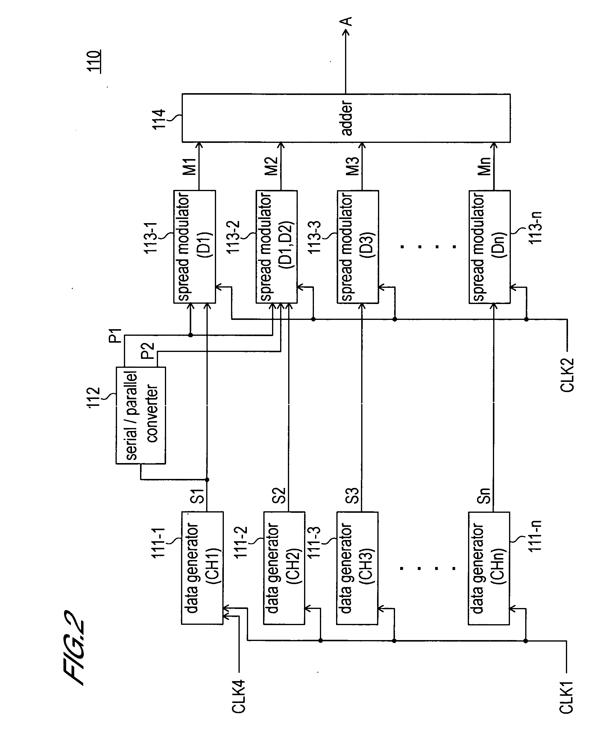
A code division multiplexing communication system which transmits a single signal array in use of band for two channels. A first data generator generates a channel signal array. A data distributor branches the channel signal array into two. A first spread modulator converts one of the branch signal array to a signal array having values VL and VH by performing spread modulation in use of a predetermined spread code. A second spread modulator converts the other branch signal array to a signal array having signal values VL, VH and high impedance and then performs spread modulation in use of the same spread code as the first spread modulator. The outputs of the first and the second spread modulator are piled by an adder. Accordingly, a quaternary signal array using band for two channels can be generated.

Description

BACKGROUND OF THE INVENTION [0001] 1. Field of the Invention [0002] The present invention relates to a communication system which performs signal multiplexing in use of a Code Division Multiplexing (CDM) method. [0003] 2. Description of Related Art [0004] Conventionally, as a technique for multiplexing signal arrays of a plurality of channels, a Code Division Multiplexing method is known. As the Code Division Multiplexing method, such as Synchronous Code Division Multiplexing method, Asynchronous Code Division Multiplexing method and Quasi-Synchronous Code Division Multiplexing method are known. The Synchronous Code Division Multiplexing method is superior to other methods in that the number of multiplexing in a code length (that is, the number or chips) becomes larger. As a document disclosing the Synchronous Code Division Multiplexing method, Japanese Patent Application Laid-Open No. 2004-80385 is known, for example. [0005]FIG. 9 is a schematic diagram showing an example of a comm...

Claims


Application Information

Patent Timeline
IPC IPC(8): H04B7/216H04J13/16H04J13/00
CPCH04J13/10H04J13/16
Inventor MATSUNO, KAZUHIKOKASHIMA, MASAYUKI
Owner OKI ELECTRIC IND CO LTD
Why Eureka
Try Eureka