Method and apparatus for estimating transmit weights for multiple antennas

a technology of transmit weight and antenna, applied in the field of communication, can solve problems such as complex determination of the weight of the antenna

Inactive Publication Date: 2006-07-06
NOKIA CORP
View PDF4 Cites 34 Cited by
  • Summary
  • Abstract
  • Description
  • Claims
  • Application Information

AI Technical Summary

Benefits of technology

[0007] According to one aspect of an embodiment of the present invention, a method for supporting transmission over a radio communication system is disclosed. The method includes applying an antenna weight vector to a plurality of antennas, wherein the antenna weight vector is generated by minimizing a cost function based on a transmitted signal and an estimated signal at a receiver. The cost function is jointly optimized according to a transmit filter and a receiver filter of the receiver. The method also includes transmitting a signal via the antennas over the radio communication system to the receiver.
[0008] According to another aspect of an embodiment of the present invention, an apparatus for supporting signal transmission is disclosed. The apparatus includes a plurality of antennas configured to transmit signals over a radio channel to a receiver. The apparatus also includes antenna weighting circuitry configured to generate an antenna weight vector by minimizing a cost function based on a transmitted signal and an estimated signal at the receiver. The cost function is jointly optimized according to a transmit filter and a receiver filter of the receiver. The circuitry is further configured to apply the generated antenna weight vector to the antennas.

Problems solved by technology

Unfortunately, the determination of these antenna weighting values can be complex in a multipath channel, particularly a frequency selective channel.

Method used


Image

  • Method and apparatus for estimating transmit weights for multiple antennas
  • Method and apparatus for estimating transmit weights for multiple antennas
  • Method and apparatus for estimating transmit weights for multiple antennas

Examples


Embodiment Construction

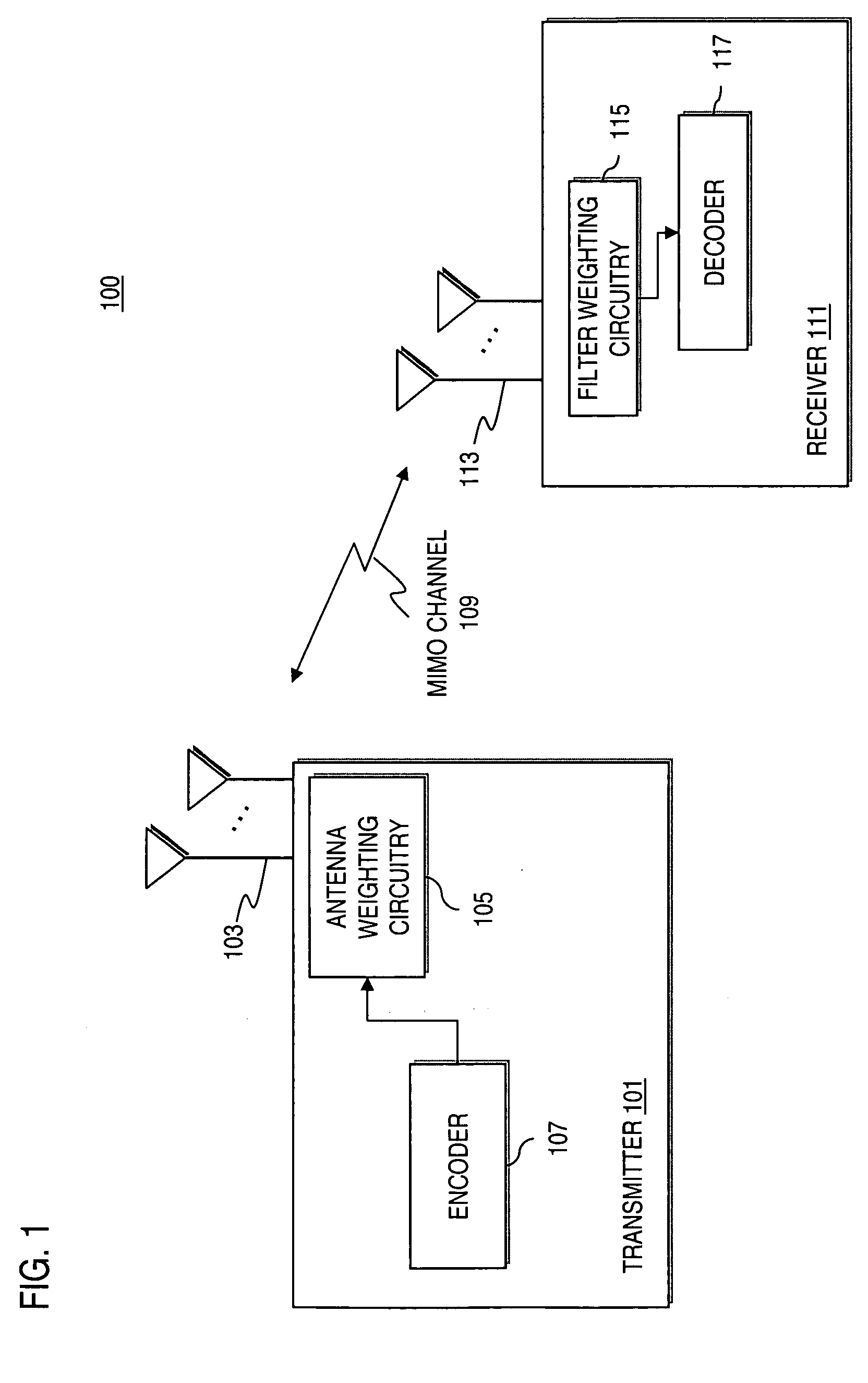
[0017] An apparatus, method, and software for determining antenna weights in a multiple antenna communication system are described. In the following description, for the purposes of explanation, numerous specific details are set forth in order to provide a thorough understanding of the present invention. It is apparent, however, to one skilled in the art that the present invention may be practiced without these specific details or with an equivalent arrangement. In other instances, well-known structures and devices are shown in block diagram form in order to avoid unnecessarily obscuring the present invention.

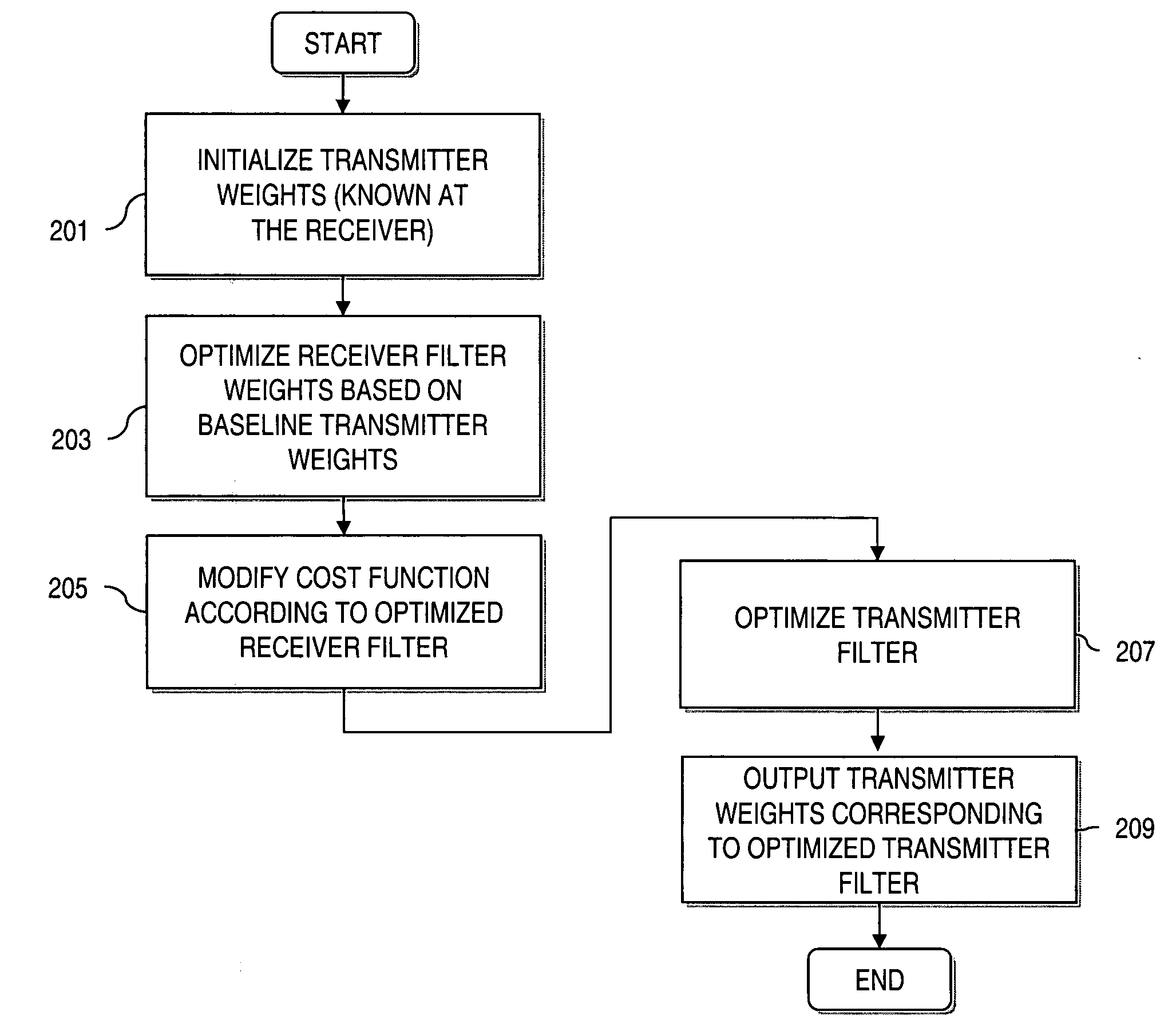
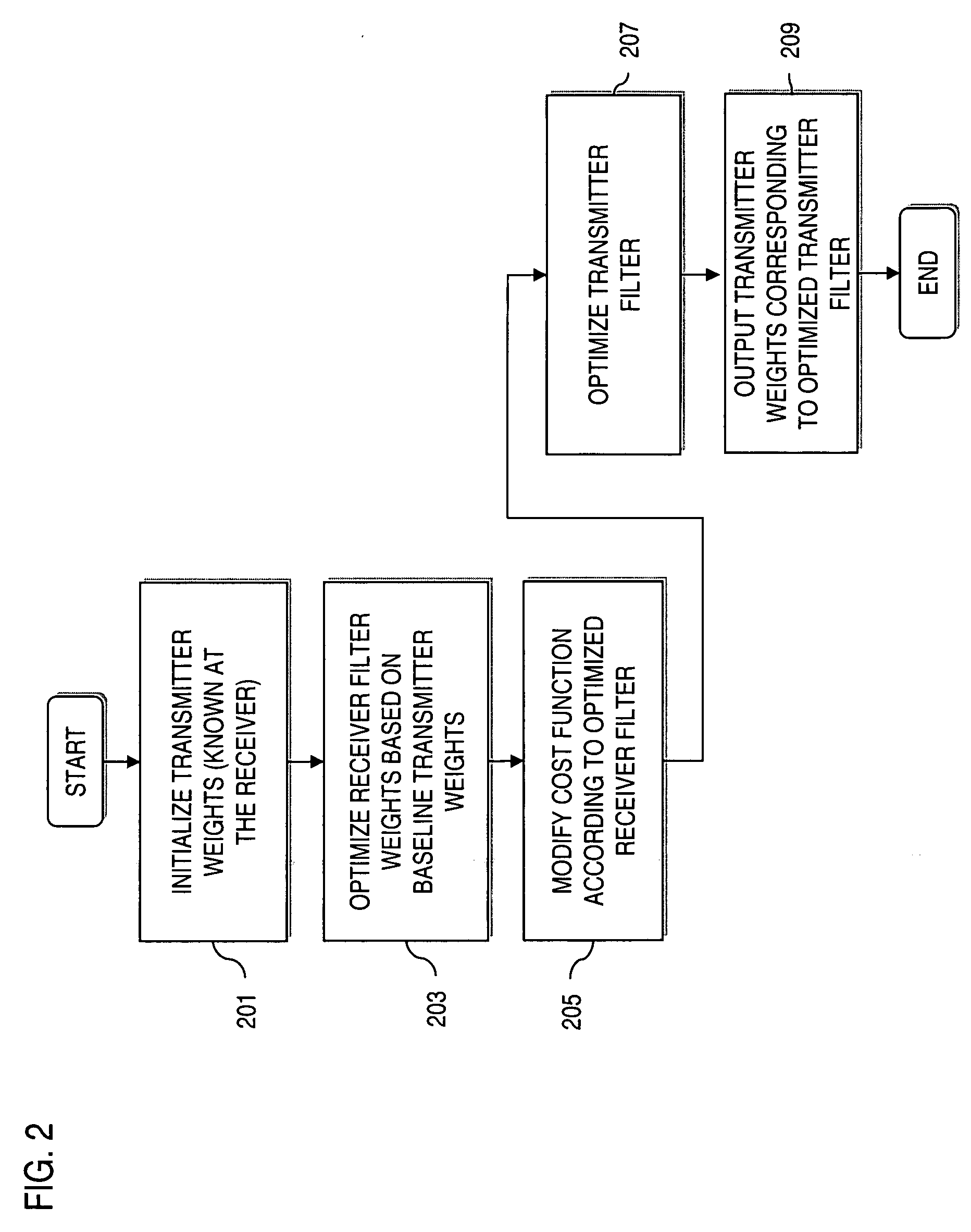
[0018] According to one embodiment of the present invention, an approach is provided for estimating the transmitter weights for a multiple antenna system, by jointly optimizing the transmitter weights and the receiver filter. In an exemplary embodiment, the cost function used is the mean squared of the difference between the transmitted signal and the estimated signal. This ap...


PUM


Abstract

An approach for determining antenna weights in a multiple antenna communication system is provided. The approach jointly optimizes the transmitter weights and the receiver filter. A filter of a receiver (e.g., Linear Minimum Mean Square Error (LMMSE)) is optimized using initial weight values of the transmit antennas. The cost function, which is a mean-squared of a difference between a transmitted signal and an estimated signal, is then modified according to the optimized receiver filter. A transmit filter is then optimized according to the modified cost function. The above approach advantageously can obtain antenna weights when the condition of separability of paths does not exist.

Description

RELATED APPLICATIONS [0001] This application is related to, and claims the benefit of the earlier filing date under 35 U.S.C. § 119(e) of, U.S. Provisional Patent Application (Ser. No. 60 / 640,647) filed Dec. 30, 2004, entitled “Method and Apparatus for Estimating Transmit Weights for Multiple Antennas”; the entirety of which is incorporated herein by reference.FIELD OF THE INVENTION [0002] The present invention relates to communications, and more particularly, to a multiple antenna transmission system. BACKGROUND OF THE INVENTION [0003] Multiple antenna communication systems have emerged to address the continual need for greater network capacity and availability by exploiting transmit diversity. Such systems are referred to as Multiple Input Multiple Output (MIMO) systems, and can encompass a multiple antenna configuration at the transmitter and a multiple or single antenna configuration at the receiver. MIMO systems improve system capacity by transmitting different data streams ove...

Claims


Application Information

Patent Timeline
Patent Type & Authority Applications(United States)
IPC IPC(8): H04B7/02
CPCH04B7/0413H04B7/0854
Inventor RAGHOTHAMAN, BALAJIZHANG, JIANZHONGWANG, YANLAMPINEN, MARKO
Owner NOKIA CORP
Why Eureka
Try Eureka