
User interface for a remote control application

a remote control and user interface technology, applied in the field of hand-held electronic devices, can solve the problems of increasing complexity of the user interface reducing the usability of the universal remote control, and increasing complexity

Inactive Publication Date: 2006-07-06
UNIVERSAL ELECTRONICS INC
View PDF87 Cites 116 Cited by
  • Summary
  • Abstract
  • Description
  • Claims
  • Application Information

AI Technical Summary

Benefits of technology

The present invention relates to an improved design for remotely controllable electronic devices like PDAs (personal digital assistants) or other similar products. This new design provides users with better access and visual cues about how they can use their device's remote control function. It allows them to easily operate it without requiring extensive training or technical knowledge. Overall, this innovation simplifies the process of learning and utilizing advanced technology through its intuitive user interface.

Problems solved by technology

The technical problem addressed in this patent is how to improve the user experience when using a universal remote control with a large amount of operational capabilities. With each new appliance added, the user interface can become too complicated, making it difficult to use effectively. There is a need for a simplified way to operate these remote controls while still maintaining their functionality.

Method used


Image

  • User interface for a remote control application
  • User interface for a remote control application
  • User interface for a remote control application

Examples


Embodiment Construction

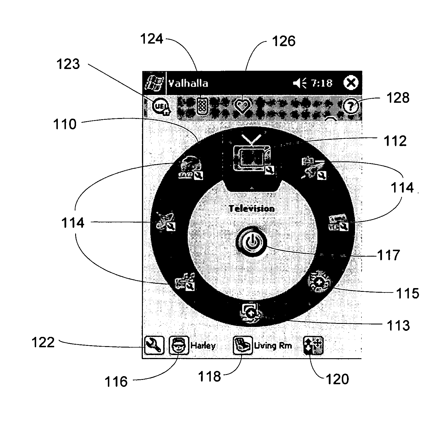
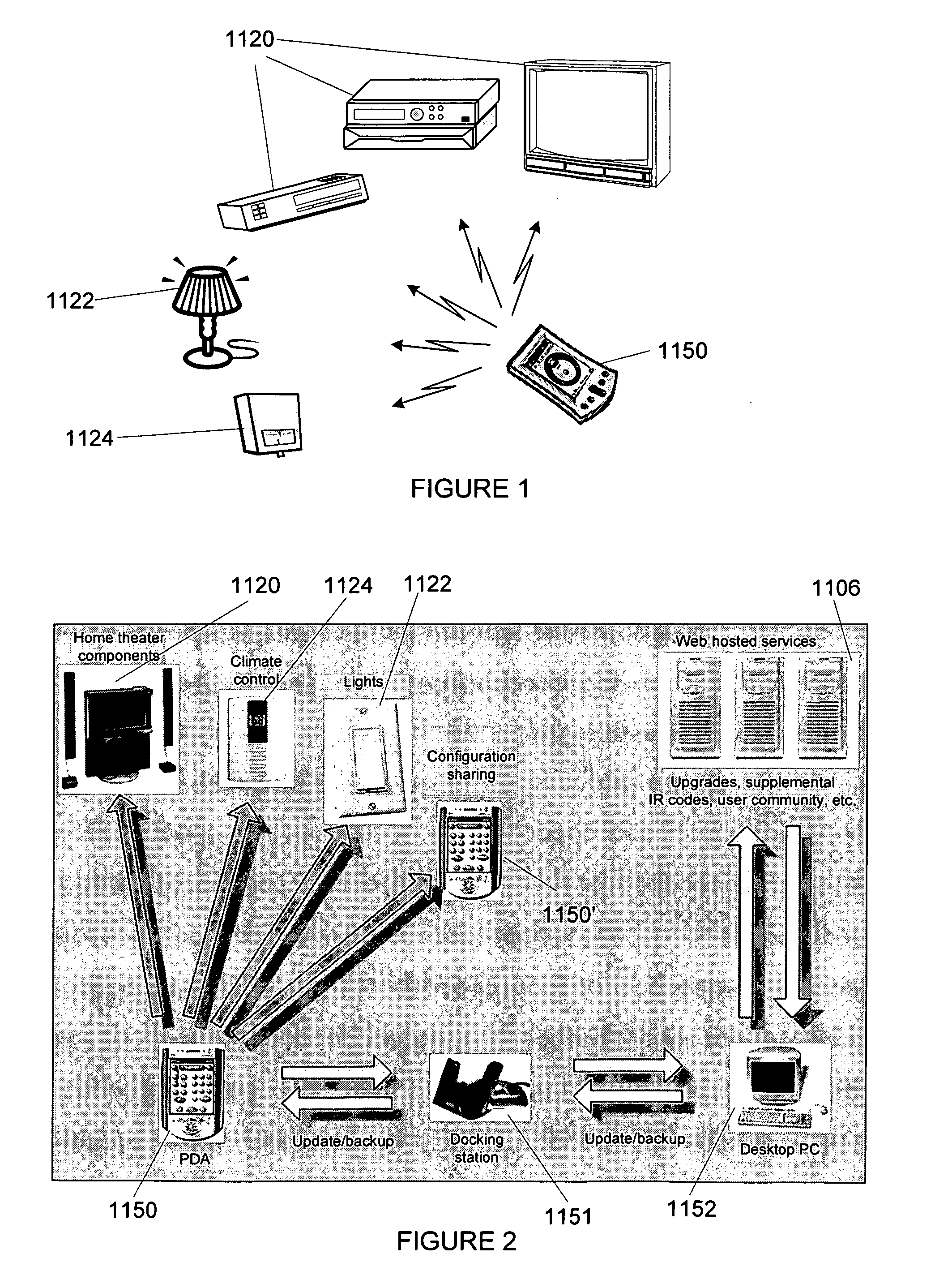
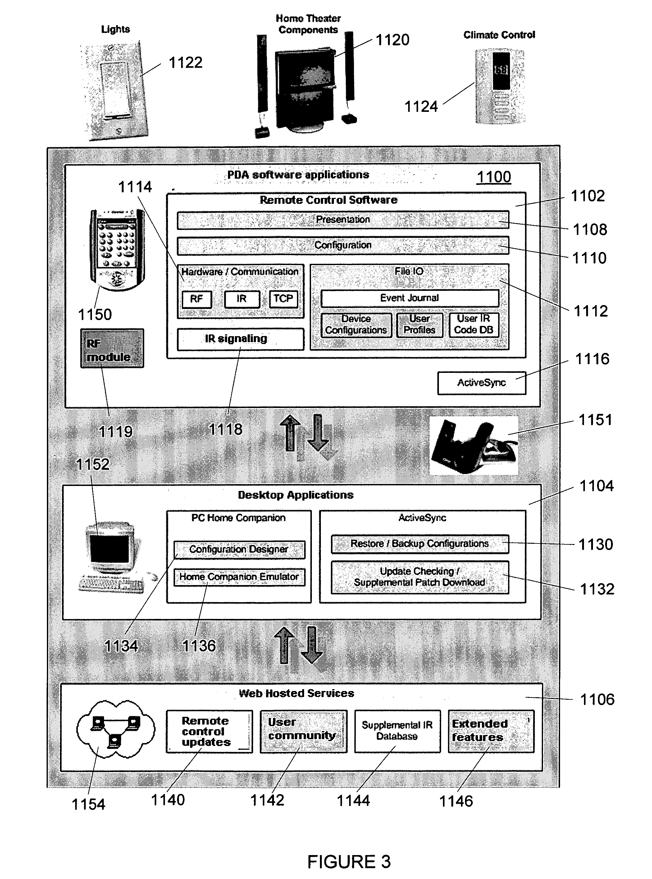
[0029] Exemplary embodiments of a user interface for an universal remote control application resident on the hand-held electronic device are illustrated and described which provide a next generation of home automation and consumer electronic controls. Representative platforms for the hand-held electronic device include devices supporting the Windows CE brand operating system or PocketPC type devices that include built-in support for transmitting consumer equipment IR remote control codes. Exemplary devices include, but are not limited to, devices such as the Compaq (now HP) iPAQ brand model 3950 or 3970 that include a hardware module to house the IR transmitter and an IR database of consumer electronics command codes, along with a remote control application that is used to control the operations of various consumer appliances. Other platform implementations using either built-in or add-on hardware to implement the IR transmit functionality are also possible, using other Windows CE b...


PUM


Abstract

A hand-held electronic device having a remote control application user interface that functions to displays operational mode information to a user. The graphical user interface may be used, for example, to setup the remote control application to control appliances for one or more users in one or more rooms, to perform activities, and to access favorites. The remote control application is also adapted to be upgradeable. Furthermore, the remote control application provides for the sharing of operational mode information.

Description


Claims


Application Information

Patent Timeline
Owner UNIVERSAL ELECTRONICS INC
Learn More