Split rotor system and method with springs

a rotor and spring technology, applied in the direction of circuit-breaking switches, contacts, circuit-breaking switches for excess current, etc., can solve the problems of high assembly time, system requirements for complex assembly jigs and fixtures, and does not meet top-down assembly criteria

Active Publication Date: 2006-07-13
ABB SPA
View PDF7 Cites 33 Cited by
  • Summary
  • Abstract
  • Description
  • Claims
  • Application Information

AI Technical Summary

Problems solved by technology

Such rotary assemblies are designed such that assembly time is high, and does not meet top-d

Method used


Image

  • Split rotor system and method with springs
  • Split rotor system and method with springs
  • Split rotor system and method with springs

Examples


Embodiment Construction

[0019] An embodiment of the invention provides a split rotor with spring, to reduce friction, in a double break arrangement and having a top down assembly in the manufacturing which, in result, will reduce the assembly time in an automated system. This system is accomplished through the development of a contact arrangement for a frame breaker, with fewer components and less assembly time to reduce the cost of the breaker. Thus, a double contact rotor system is provided that will deliver equal contact force regardless of contact wear, electrical isolation from adjacent electrical phases and few parts for ease of manufacture. In result, the whole pole enclosure assembly is a top down assembly.

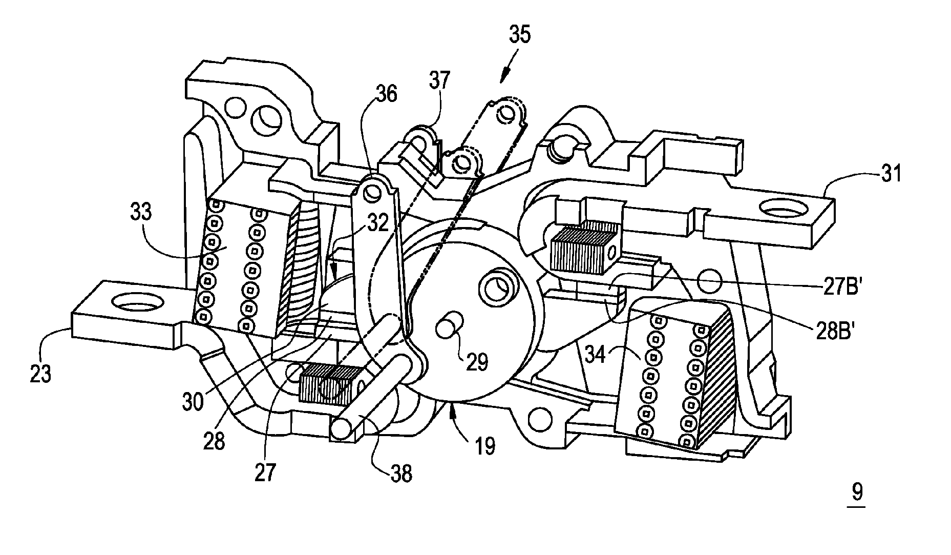
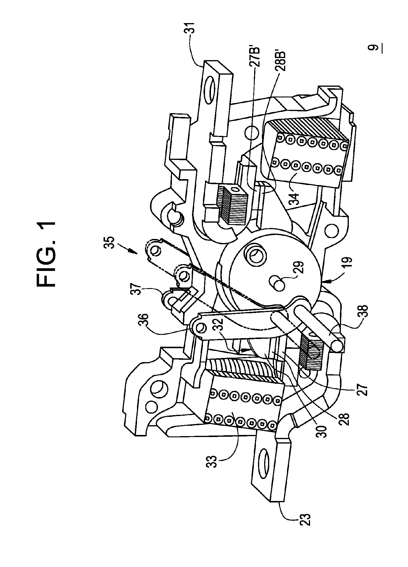
[0020]FIG. 1 shows an exemplary circuit breaker rotary contact assembly 10 that may employ the split rotor with spring. While only one embodiment of a circuit breaker rotary contact assembly 9 is shown, it should be understood that the split rotor with spring may be utilized in alternate embodim...


PUM


Abstract

A rotor assembly may include first rotor half, a first spring supported with the first rotor half, a second rotor half, and a second spring supported within the second rotor half, wherein the first rotor half and the second rotor half are adjoined to enclose the first and second springs. A coiled section of each spring may surround a rotor center pin. A contact arm positioned between the springs may include a non-circular opening. A method for assembling such a rotor assembly is further described.

Description

BACKGROUND OF THE INVENTION [0001] The present disclosure relates generally to a contact assembly, and particularly to a rotor assembly for a contact assembly. [0002] Contact pairs are commonly arranged upon one movable rotary contact arm. When an overcurrent condition exists, electromagnetic forces cause the rotary contact arm to separate from fixed contacts against the closing force of one or more contact springs. [0003] The rotary contact arm is typically connected to the contact springs via pivotal links. During quiescent operation, the contact springs provide a force to the rotary contact arm via the links in a direction as to drive the rotary contact arm into the fixed contacts. Upon short circuit condition, for example, current levels at or above the “withstand level” of the interrupter, the electromagnetic forces generated between the fixed contacts and the rotary contact arm causes the rotary contact arm to rotate away from the fixed contacts. If the overcurrent level reach...

Claims


Application Information

Patent Timeline
IPC IPC(8): H01H75/00H01H77/00
CPCH01H1/205H01H1/2058H01H73/045H01H2001/223
Inventor RAJAURIA, SAMIRMEYER-HAACK, WOLFGANGNARAYANAN, JANAKIRAMANBHATTACHARJEE, SANJOYANJARIA, HERMANTVERMA, PRAVEENKUMAR
Owner ABB SPA
Why Eureka
Try Eureka