Counter track joint

a counter-track joint and counter-speed technology, applied in the direction of couplings, mechanical devices, rotary machine parts, etc., can solve the problems of weakening the ball cage and reducing the web width between, so as to increase the load bearing capacity of the inventive joint, widen the web, and increase the strength of the cage in operation.

Active Publication Date: 2006-07-13
GKN DRIVELINE INT GMBH
View PDF10 Cites 4 Cited by
  • Summary
  • Abstract
  • Description
  • Claims
  • Application Information

AI Technical Summary

Benefits of technology

[0008] As a result of the inventive widened, non-contacting assembly regions at the ends of the second outer ball tracks, it is possible to insert the balls of a second group of balls when the cage is articulated only slightly beyond the maximum operating angle of articulation relative to the outer joint part. Advantageously, the first cage windows for an already inserted first group of balls need to be increased only slightly beyond their circumferential length required for operational purposes. The cage windows for the second group of balls can comprise a shorter circumferential length because the balls inside these windows are not displaced relative to one another during assembly. During assembly, as the balls of the second group are positioned on the articulation axis of the joint on the one hand, and on the articulation plane of the joint on the other hand, they merely require the minimum length needed for articulation purposes within the operating range of articulation. It is thus possible to widen the webs between the cage windows considerably, thereby increasing the strength of the cage in operation. The load bearing capacity of the inventive joint is thus also increased.
[0009] According to a further advantageous embodiment which requires particularly large widened, non-contacting assembly regions, four first cage windows associated with the first pairs of tracks, comprise a length L1 in the circumferential direction. Four second cage windows associated with the second pairs of tracks have a corresponding circumferential lengths L2. The lengths L1, L2 are adapted to the operating angle of articulation of the joint, but also include a small excess dimension. The excess dimension from L1 and L2 can be the same or different. In this embodiment, the assembly process is the same as described above, with one advantage being that the cage can be inserted as desired, relative to the first and second pairs of tracks.

Problems solved by technology

There are certain disadvantages associated with the assembly of constant velocity joints wherein first the outer joint part, cage and inner joint part are joined in one of the ways commonly known.
Such lengthening of the cage windows in the circumferential direction leads to a reduction in the web width between the cage windows in the circumferential direction, and thus to a weakening of the ball cage.

Method used


Image

  • Counter track joint
  • Counter track joint
  • Counter track joint

Examples


Embodiment Construction

[0037] In the following figures, the same reference numerals are used to refer to the same components in the various views. Also, in the following description, various operating parameters and components are described for several embodiments. These parameters and components are included as examples and are not meant to be limiting.

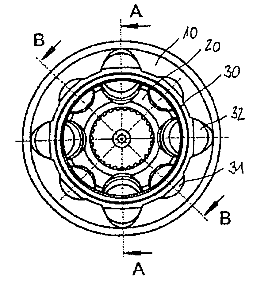
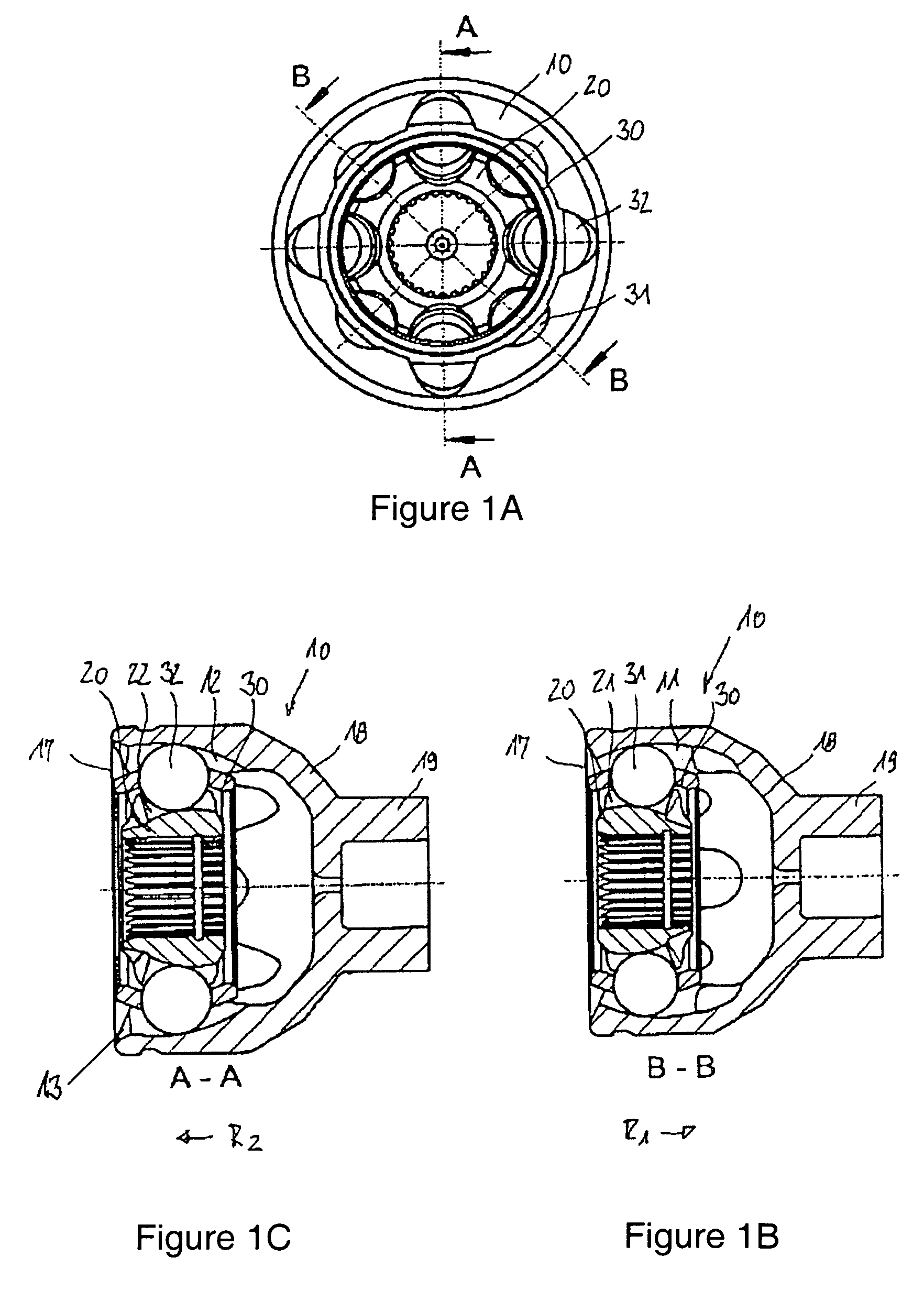
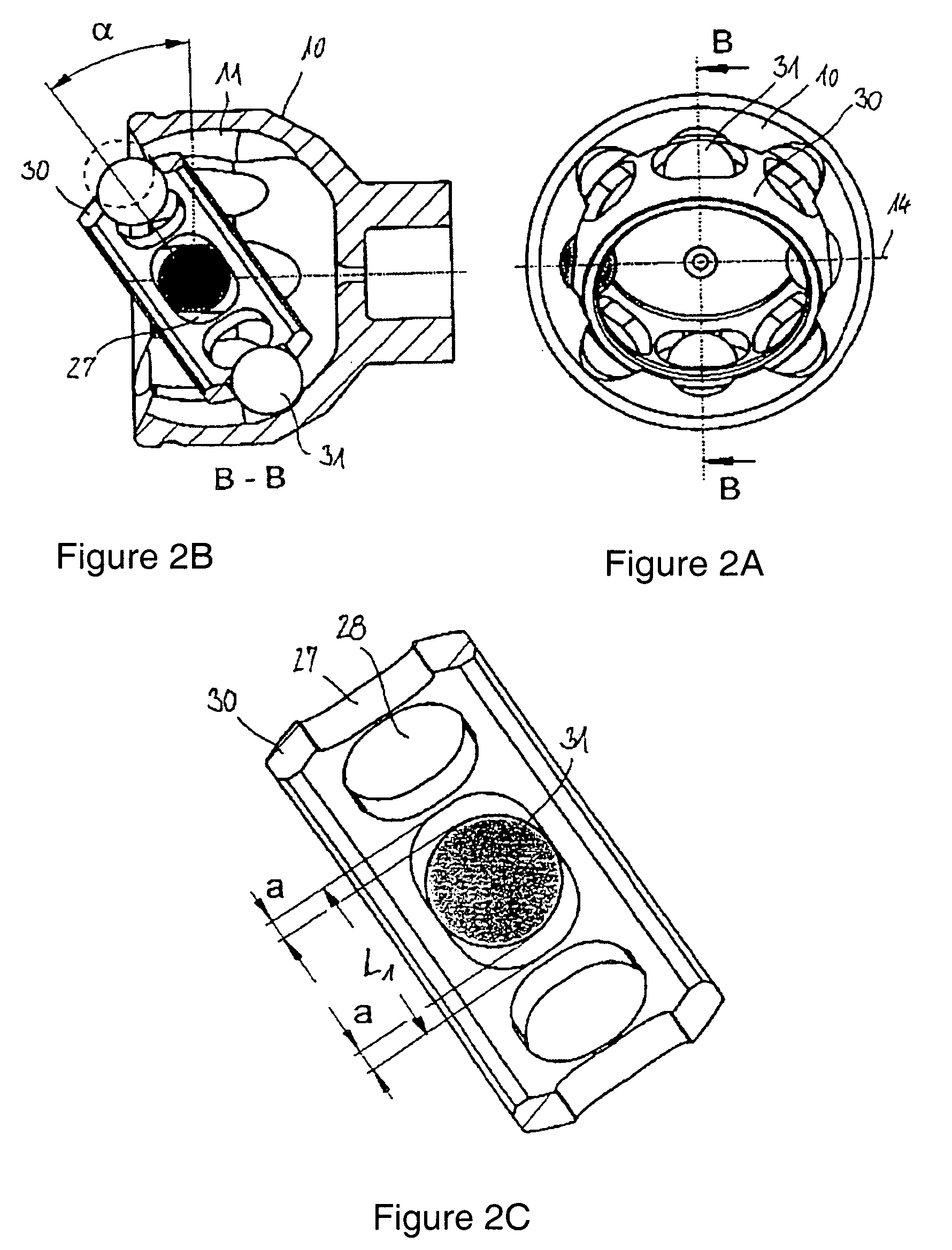
[0038] The three individual illustrations of FIG. 1 will be described jointly below. The figures illustrate a constant velocity fixed ball joint and, more particularly, a counter track joint with eight balls. In the embodiment illustrated here, an outer joint part 10 comprises a joint aperture 17 and a base 18 with a formed-on journal 19. The base 19 is axially opposed to the aperture 17. The outer joint part 10 is provided with first outer ball tracks 11 and second outer ball tracks 12, each having four ball tracks being alternately distributed across the circumference. The outer joint part 10 accommodates a ball cage 30 and an inner joint part 20. In th...


PUM

PropertyMeasurementUnit
angleaaaaaaaaaa
angle β2aaaaaaaaaa
torqueaaaaaaaaaa

Abstract

A counter track joint having an outer joint part (10), inner joint part (20), a ball cage (30) and torque transmitting balls. First outer tracks and first inner tracks form first pairs of tracks which widen in a first direction, and second outer tracks and second inner tracks form second pairs of tracks which widen in an opposed second direction. The annular cage (30) includes four first and four second circumferentially distributed cage windows which each accommodate one of the balls and which hold the balls in one plane. The second outer ball tracks (12), at one end, include widened, non-contacting assembly portions (13) for inserting balls (32) into the second cage windows from the radial outside, with all the first cage windows already having balls, and with the second cage windows axially projecting from the outer joint part (10) as a result of the joint being over-articulated.

Description

CROSS-REFERENCE TO RELATED APPLICATION [0001] This application is a Continuation-In-Part of U.S. patent application Ser. No. 10 / 770,191 entitled “Counter Track Joint” and filed on Feb. 2, 2004.TECHNICAL FIELD [0002] The present invention relates to constant velocity joints and, more particularly, concerns constant velocity joint assemblies having improved construction. BACKGROUND OF THE INVENTION [0003] Constant velocity fixed ball joints in the form of counter track joints, have an outer joint part with outer tracks, an inner joint part with inner tracks, torque transmitting balls which are received in pairs of tracks consisting of outer tracks and inner tracks, and a ball cage with cage windows in which the balls are held in a common plane and are guided on to the angle-bisecting plane when the joint is articulated. In such joints, first outer tracks, together with first inner tracks, form first pairs of tracks whose control angles open in a first axial direction, and second outer...

Claims


Application Information

Patent Timeline
Patent Type & Authority Applications(United States)
IPC IPC(8): F16D3/34F16D3/223
CPCF16D3/223F16D2003/22303Y10S464/906Y10T29/49826F16D2003/22306
Inventor HASSENRIK, IDAMAUCHER, STEPHANWECKERLING, THOMAS
Owner GKN DRIVELINE INT GMBH
Why Eureka
Try Eureka