Constant velocity ball joint with ball pairs whose tracks are located on symmetrical planes

a constant velocity, ball joint technology, applied in mechanical equipment, yielding couplings, rotary machine parts, etc., can solve the problems of reducing the width of the web between the cage windows and weakened cages, and achieve the greatest possible torque transmission capacity and high efficiency

Inactive Publication Date: 2006-04-11
GKN LOBRO
View PDF11 Cites 6 Cited by
  • Summary
  • Abstract
  • Description
  • Claims
  • Application Information

AI Technical Summary

Benefits of technology

[0005]It is the object of the present invention to provide a compact fixed joint for being accommodated in a predetermined space and having a greatest possible torque transmitting capacity and a high efficiency. In particular, it should be possible to produce said constant velocity fixed joint economically.

Problems solved by technology

In consequence, the width of the webs between the cage windows is reduced and the cage is weakened.

Method used


Image

  • Constant velocity ball joint with ball pairs whose tracks are located on symmetrical planes
  • Constant velocity ball joint with ball pairs whose tracks are located on symmetrical planes
  • Constant velocity ball joint with ball pairs whose tracks are located on symmetrical planes

Examples


Embodiment Construction

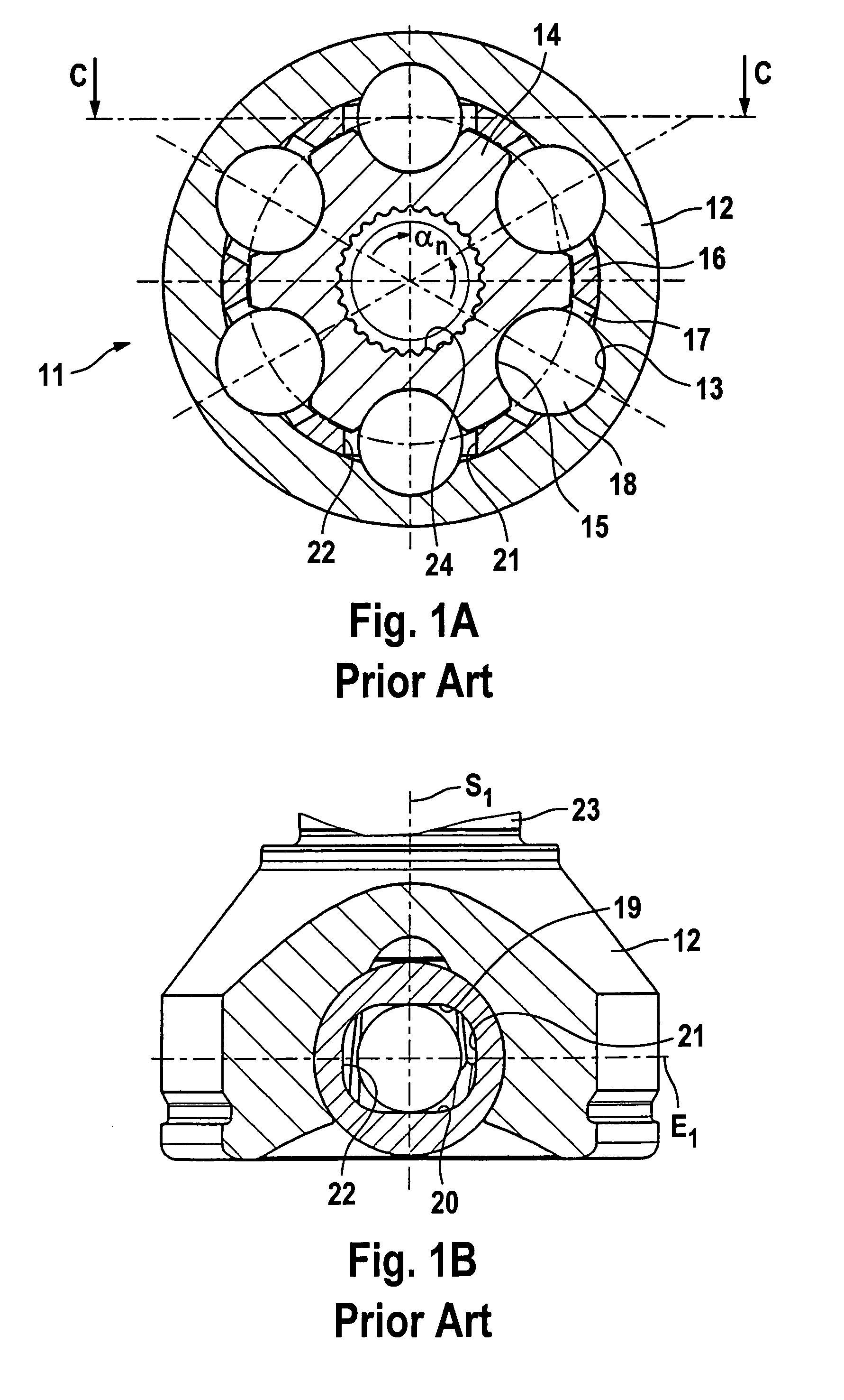
[0044]FIG. 1 shows a constant velocity fixed joint 11 according to the state of the art in the form of a joint with six balls, comprising an outer joint part 12 with outer ball tracks 13, an inner joint part 14 with inner ball tracks 15, a ball cage 16 with cage windows 17 and balls 18 received in the latter. The cage windows comprise circumferentially extending parallel ball contact guiding flanks 19, 20 as well as ball contact end flanks 21, 22 connecting the latter. The respective pairs of flanks 19, 20; 21, 22 are arranged parallel relative to one another. Outer ball tracks 13 and inner ball tracks 15 which are associated with one another form sets of tracks in the sense as used in this Application. The angular distance between the individual pairs of tracks amounts to αn in all cases. The centers of the balls 18 are positioned in the central ball plane E1. The longitudinal axes have jointly been given the reference symbol S1.

[0045]At the outer joint part 12, there is formed on ...


PUM


Abstract

A constant velocity fixed ball joint provided with an outer joint with outer tracks and an inner joint part with inner tracks. The outer tracks and inner tracks form sets of tracks, with a torque transmitting ball being guided in each set of tracks. A ball cage accommodates the balls in circumferentially distributed cage windows and, when the joint is articulated, guides the balls on to the angle-bisecting plane between the longitudinal axes. The cage windows each accommodate pairs of balls. When the joint is in the aligned condition, in the central joint plane, the angular distance of the balls within the individual pairs of balls is smaller than the angular distance between balls associated with pairs adjoining one another; and the center lines of the sets of tracks of the pairs of balls extend in planes which extend parallel relative to one another.

Description

Background Of The Invention[0001]The invention relates to a constant velocity fixed ball joint provided with an outer joint part having a first longitudinal axis and an inner chamber with outer tracks extending in said inner chamber in the longitudinal direction; provided with an inner joint part having a second longitudinal axis and forming a hub member with inner tracks extending on said hub member in the longitudinal direction; the outer tracks and inner tracks form sets of tracks, with a torque transmitting ball being guided in each set of tracks; the outer tracks and inner tracks each comprise curved center lines, with the center lines of the individual sets of tracks of an aligned joint intersecting one another in the central joint plane positioned normally relative to the longitudinal axes; a ball cage accommodates the balls in circumferentially distributed cage windows and, when the joint is articulated, guides the balls on to the angle-bisecting plane between the longitudin...

Claims


Application Information

Patent Timeline
Patent Type & Authority Patents(United States)
IPC IPC(8): F16D3/224F16D3/223F16D3/2237F16D3/229
CPCF16D3/2237F16D3/229Y10S464/906F16D2003/22309F16D2003/22306
Inventor SCHWARZLER, PETER
Owner GKN LOBRO
Why Eureka
Try Eureka