Energy absorbing webbings

a technology of webbing, which is applied in the field of webbing, can solve the problems of two separate webbings, people who are at elevated positions above a floor or other relatively lower surface, and can be at risk of falling and injury, and achieve the effects of improving energy or shock absorption webbing, improving tear-away shock absorption webbing, and improving webbings

Active Publication Date: 2010-06-01
YKK CORP OF AMERICA
View PDF78 Cites 31 Cited by
  • Summary
  • Abstract
  • Description
  • Claims
  • Application Information

AI Technical Summary

Benefits of technology

[0040]One advantage of the present invention is to provide improved webbings, such as, improved energy or shock absorbing webbings and improved tear-away shock absorbing webbings.
[0041]An advantage of the present invention is to provide a one-piece tear-away energy absorbing webbing.
[0042]Another advantage of the present invention is to provide improved tear-away energy absorbing webbings which have top and bottom layer load-bearing webs and shock absorbing binder yarns woven together as a one-piece webbing.
[0043]Yet another advantage of the present invention is to provide lanyards which can stop a person's fall while reducing the shock force to the person.
[0044]Further advantages of the present invention are to improve manufacturing of webbings and reduce costs of webbings.
[0045]Another advantage of the present invention is to provide an energy absorbing webbing made of a one-piece webbing that is torn apart during activation into two load-bearing webs.

Problems solved by technology

People who are at elevated positions above a floor or other relatively lower surface can be at risk of falling and injury.
For example, workers and other personnel who have occupations which require them to be at elevated positions, such as on scaffolding, can be at risk of falling and injury.
The two separate webbings increase the cost of the lanyard.
Also, the process of assembling the two separate webbings increases the cost of the lanyard.
The existing tear-away lanyards having a tear-away webbing and a separate strength webbing are costly and tedious to manufacture.
For example, the longitudinal tearing or cutting of the webbing can be inconsistent and difficult to control.
The tearing or cutting action can be rather unpredictable.
Accordingly, the amount of force required to activate the lanyard can be inconsistent and unpredictable.

Method used


Image

  • Energy absorbing webbings
  • Energy absorbing webbings
  • Energy absorbing webbings

Examples


Embodiment Construction

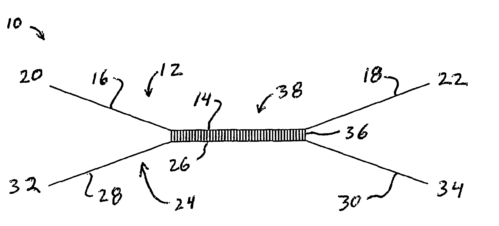
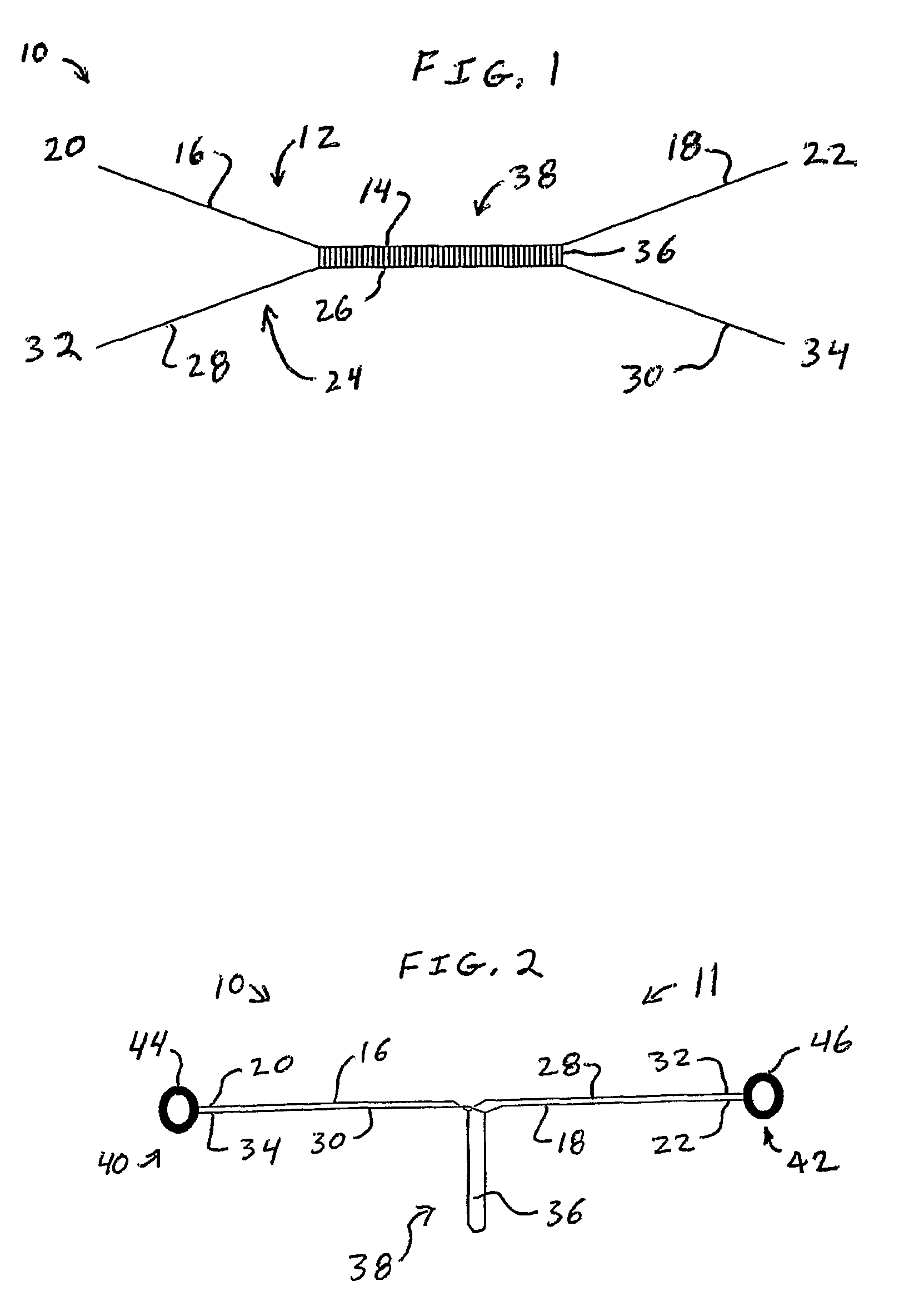
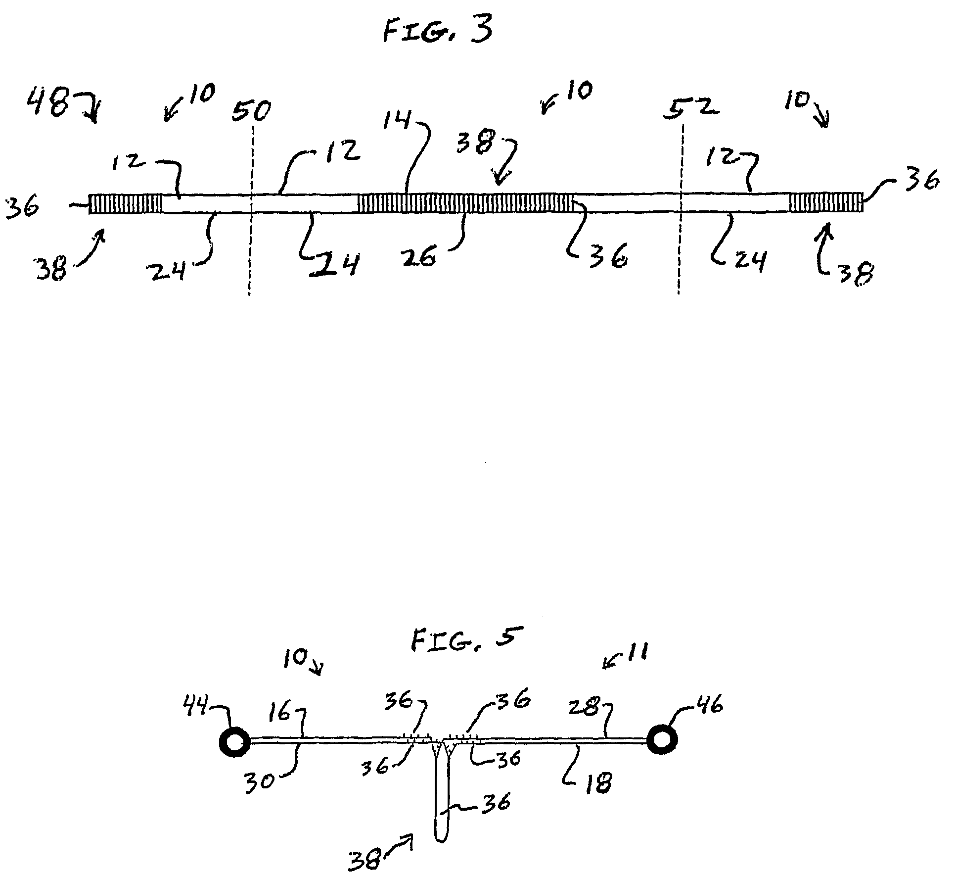
[0064]The present invention provides new webbings. The present invention particularly provides new energy absorbing webbings and new tear-away shock absorbing webbings which can absorb energy when a force is applied to the webbing. When an abrupt force is applied to the webbing, the present invention can reduce the shock of the force. One new tear-away shock absorbing webbing according to the present invention is a one-piece webbing having a top layer load-bearing web and a bottom layer load-bearing web connected together by binder yarns. The top and bottom layer load-bearing webs and the binder yarns may be simultaneously woven as a one-piece webbing. The top and bottom layer load-bearing webs are torn apart during activation of the webbing by fracture of the binder yarns to absorb energy or shock. The two torn apart load-bearing webs support the load applied to the webbing. For example, the torn-apart webs can stop a person's fall and support the final load. The present invention,...


PUM

PropertyMeasurementUnit
tensile loadaaaaaaaaaa
tensileaaaaaaaaaa
energyaaaaaaaaaa

Abstract

A tear-away energy absorbing webbing (10) is a one-piece webbing. The tear-away energy absorbing webbing (10) has a top layer load-bearing web (12) and a bottom layer load-bearing web (24). An energy absorbing portion (38) of the webbing has binder yarns (36) interlaced with the top and bottom layer load-bearing webs (12, 14). A sufficiently high load force applied to the webbing breaks the binder yarns (36) and tears apart the top and bottom layer load-bearing webs (12, 14). The energy absorbing portion (38) absorbs energy as it tears apart. The top and bottom layer load-bearing webs (12, 14) support the load force when the shock absorbing portion is torn apart.

Description

BACKGROUND OF THE INVENTION[0001]The present invention generally pertains to webbings. More specifically, the present invention pertains to energy absorbing webbings and tear-away shock absorbing webbings. One energy absorbing webbing is a one-piece webbing having two load-bearing webs connected together by binder yarns. The two load-bearing webs and the binder yarns are woven together as a one-piece webbing. During activation of the webbing, the binder yarns break as the two webs tear apart from each other and absorb energy or shock. The two torn-apart separate load-bearing webs support the load applied to the webbing. The present invention further pertains to methods of making energy absorbing webbings and methods of using energy absorbing webbings. The present invention provides improved webbings which can absorb energy and support a load.[0002]The present invention is described as being energy absorbing as well as shock absorbing. Use of the terms “energy absorbing” and “shock a...

Claims


Application Information

Patent Timeline
Patent Type & Authority Patents(United States)
IPC IPC(8): A47L3/04A62B1/16A62B35/04D03D11/02D03D17/00D03D23/00
CPCA62B35/04F16F7/006E06C7/186
Inventor JENNINGS, JOHN E.RUSSELL, TIMOTHY M.
Owner YKK CORP OF AMERICA
Why Eureka
Try Eureka