
Apparatus and method for measuring gap bulk density of a catalytic converter support mat

Inactive Publication Date: 2006-07-20
TENNECO AUTOMOTIVE OPERATING CO INC
View PDF9 Cites 17 Cited by
  • Summary
  • Abstract
  • Description
  • Claims
  • Application Information

AI Technical Summary

Benefits of technology

[0007] In another aspect of the invention, apparatus for determining gap bulk density in a catalytic converter having a cylindrical outer casing containing a converter substrate at least partially surrounded by a support mat of preselected surface area filling a gap between the outer casing and the substrate includes first and second cameras for capturing images of the gap at first and second respective opposite ends of the outer casing. A casing positioner includes a plurality of rollers positioned for abutting receipt of a converter under test, the plurality of rollers coupled to a slide mechanism for translating movement of the rollers and converter under test. A programmable controller is coupled to the casing positioner and to the first and second cameras. A scanner is coupled to the programmable contro

Problems solved by technology

However, this approach assumes no change to the mat density shortly after assembly and can lead to erroneous conclusions as to whether proper mat pressure will be applied in the final assembled product.

Method used


Image

  • Apparatus and method for measuring gap bulk density of a catalytic converter support mat
  • Apparatus and method for measuring gap bulk density of a catalytic converter support mat
  • Apparatus and method for measuring gap bulk density of a catalytic converter support mat

Examples


Embodiment Construction

[0015] The description of the invention is merely exemplary in nature and thus, variations that do not depart from the gist of the invention are intended to be within the scope of the invention. Such variations are not to be regarded as a departure from the spirit and scope of the invention.

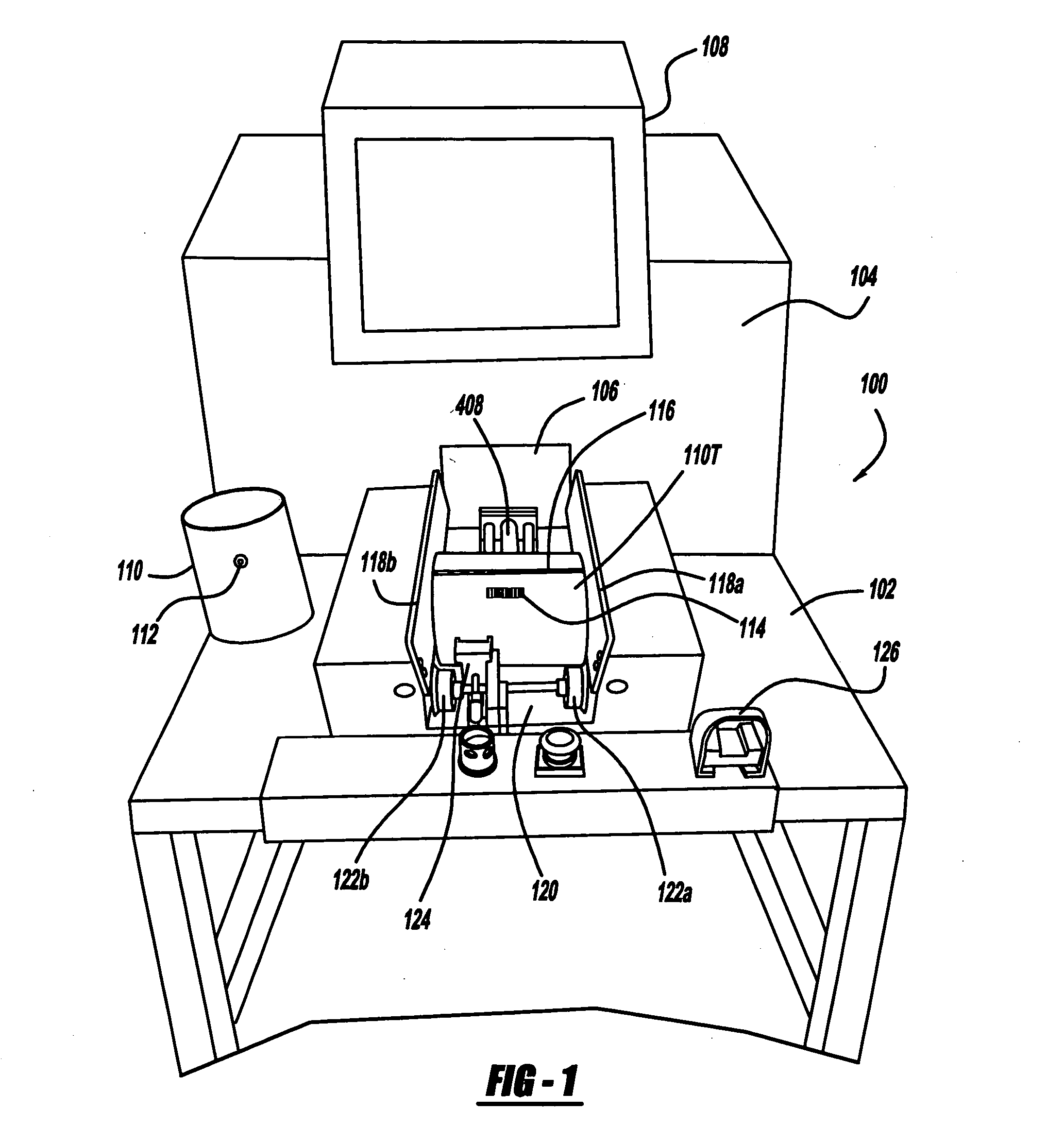
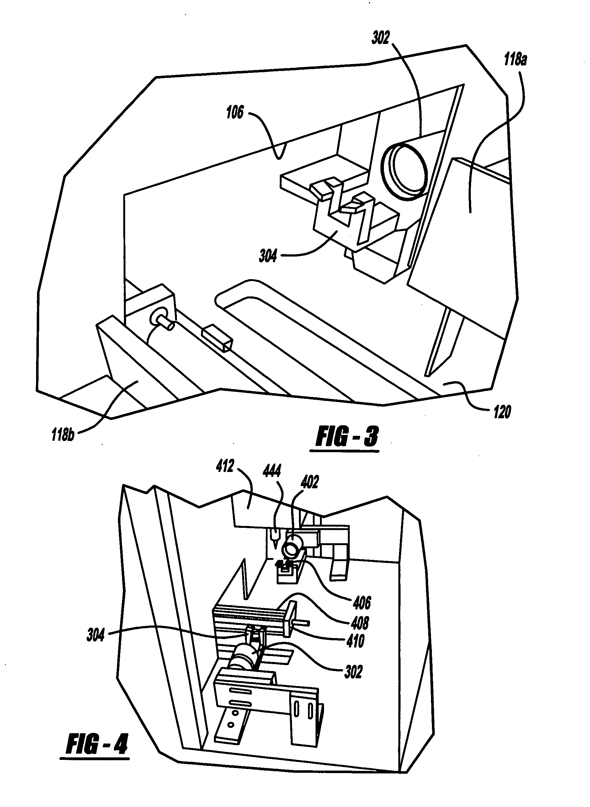
[0016] With reference to FIG. 1, GBD testing station 100 is principally comprised of a station base section 102 and a station optical measurement section 104 extending vertically from base 102. Access aperture 106 in section 104 is provided for movement of a converter under test therethrough to a gap measuring station located between first and second cameras to be discussed later.

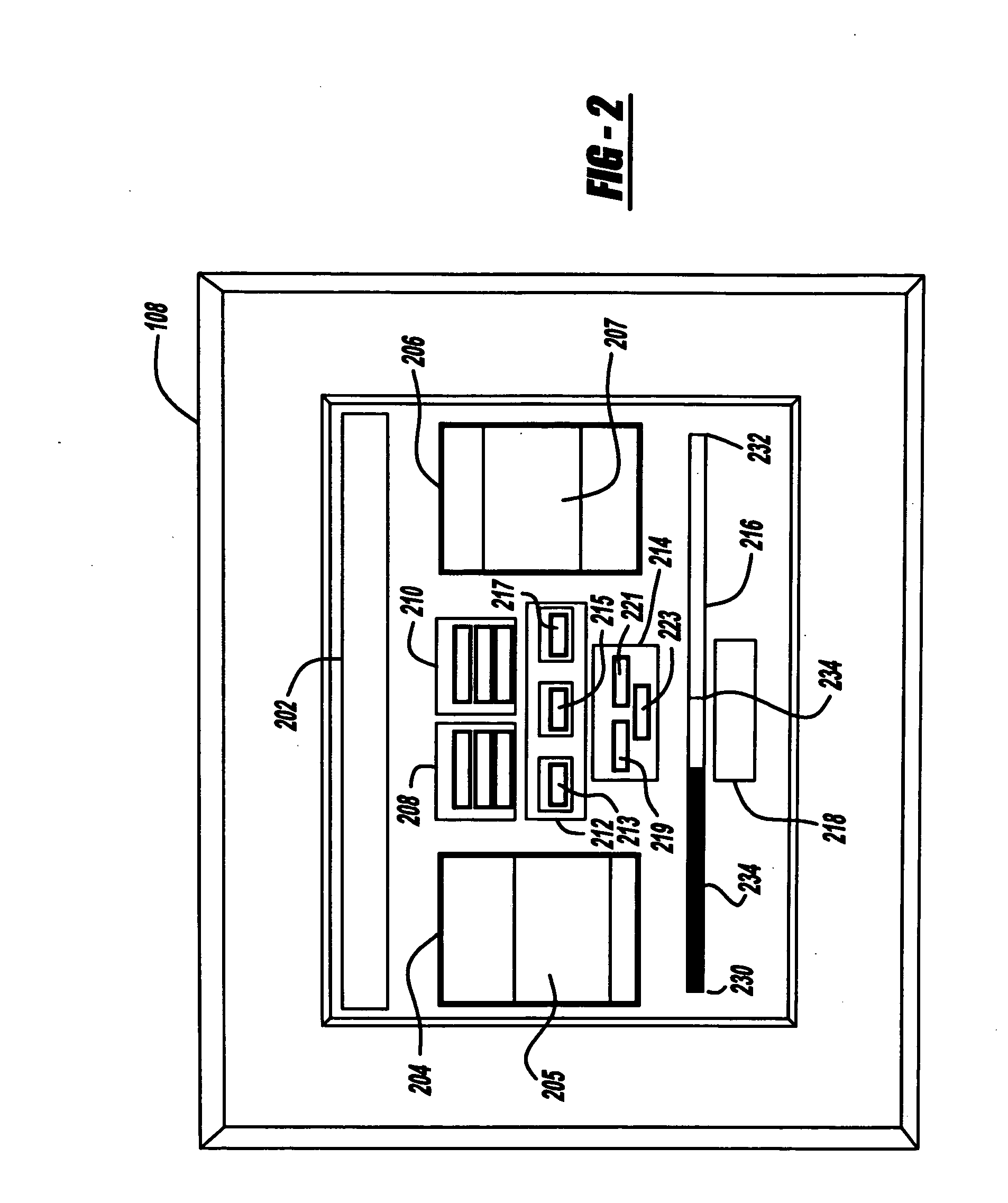
[0017] Test station display 108 is mounted to section 104 and provides a variety of information to the test stand operator, the details of which will be set forth in a later section of this description.

[0018] A typical converter outer casing 110 is shown resting on station base 102 at the left side thereof in FIG. 1. ...


PUM

PropertyMeasurementUnit
Weightaaaaaaaaaa
Densityaaaaaaaaaa
Widthaaaaaaaaaa

Abstract

Gap bulk density (GBD) of a support mat surrounding a catalyst substrate in a catalytic converter is calculated using an average gap width optically determined by a camera system. Mat weight determined at an assembly station is bar coded and placed in a bar code label attached to the converter under test. A programmable controller calculates an average gap width from a plurality of camera readings. GBD is then calculated using mat weight and dimensions, and the GBD is compared to an acceptable range to determine pass / failure of the converter.

Description

FIELD OF THE INVENTION [0001] The present invention relates to testing catalytic converters for proper assembly. More particularly, the invention concerns determining the gap bulk density of a support mat surrounding a catalyst in a converter housed in an outer casing. BACKGROUND OF THE INVENTION [0002] Many catalytic converters comprise a substrate or cartridge utilizing a structure bearing the catalytic compounds surrounded by a support mat interfacing the substrate and an outer casing or shell of the converter. In applying force to the mat by the enclosing outer shell or converter casing, two objectives are somewhat at odds. On the one hand, the pressure on the support mat must be sufficient to assure the substrate will be held in place under rather severe conditions of temperature and vibration. On the other hand, the pressure on the support mat must be less than that which would cause cracking or other damage to the substrate. [0003] One characterization of a compressed support...

Claims


Application Information

Patent Timeline
IPC IPC(8): G01N9/00B23Q17/00
CPCG01N9/00G01N2009/024Y10T29/49769Y10T29/49345Y10T29/49771
Inventor HORN, TOBIN L.WHEELER, SCOTT J.
Owner TENNECO AUTOMOTIVE OPERATING CO INC
Learn More