Drum cymbal washer

a cymbal washer and drum technology, applied in the field of drum cymbal washers, can solve the problems of limiting the movement and function of the felt washer, unsatisfactory sound of the cymbal, and the conventional method of mounting the cymbal on the cymbal stand, etc., and achieve the effect of adding rigidity and compression resistance to the washer

Inactive Publication Date: 2006-07-20
NOTTOLI BARRY J
View PDF41 Cites 8 Cited by
  • Summary
  • Abstract
  • Description
  • Claims
  • Application Information

AI Technical Summary

Benefits of technology

[0014] The present invention, generally speaking, provides for a resilient washer structure including an annulus having a top side and a bottom side; a concentric sleeve extending from the annulus; and multiple ribs extending from the sleeve on one side of the annulus and defining an upper surface of the resilient washer structure. Similar features may be formed on an opposite side of the annulus, with the ribs on opposite sides being formed in staggered alignment relative to one another. This positioning of the ribs allows the washer to compress by flexing the annulus in the space between the ribs when force is applied to the top surfaces of the ribs. A rim may be provided adjoining the terminal ends of the ribs further adding rigidity and compression resistance to the washer.

Problems solved by technology

The weight of the cymbal will over time crush the felt material thus limiting the movement and function of the felt washer.
This conventional means of mounting the cymbal on the cymbal stand has proven generally unsatisfactory.
While providing some protection of the cymbal, the felt washers tend to dampen the vibration of the cymbal, and provide unsatisfactory sound from the cymbal.

Method used


Image

  • Drum cymbal washer
  • Drum cymbal washer
  • Drum cymbal washer

Examples


Embodiment Construction

[0017] The present invention is best understood by reference to the detailed figures and description set forth herein.

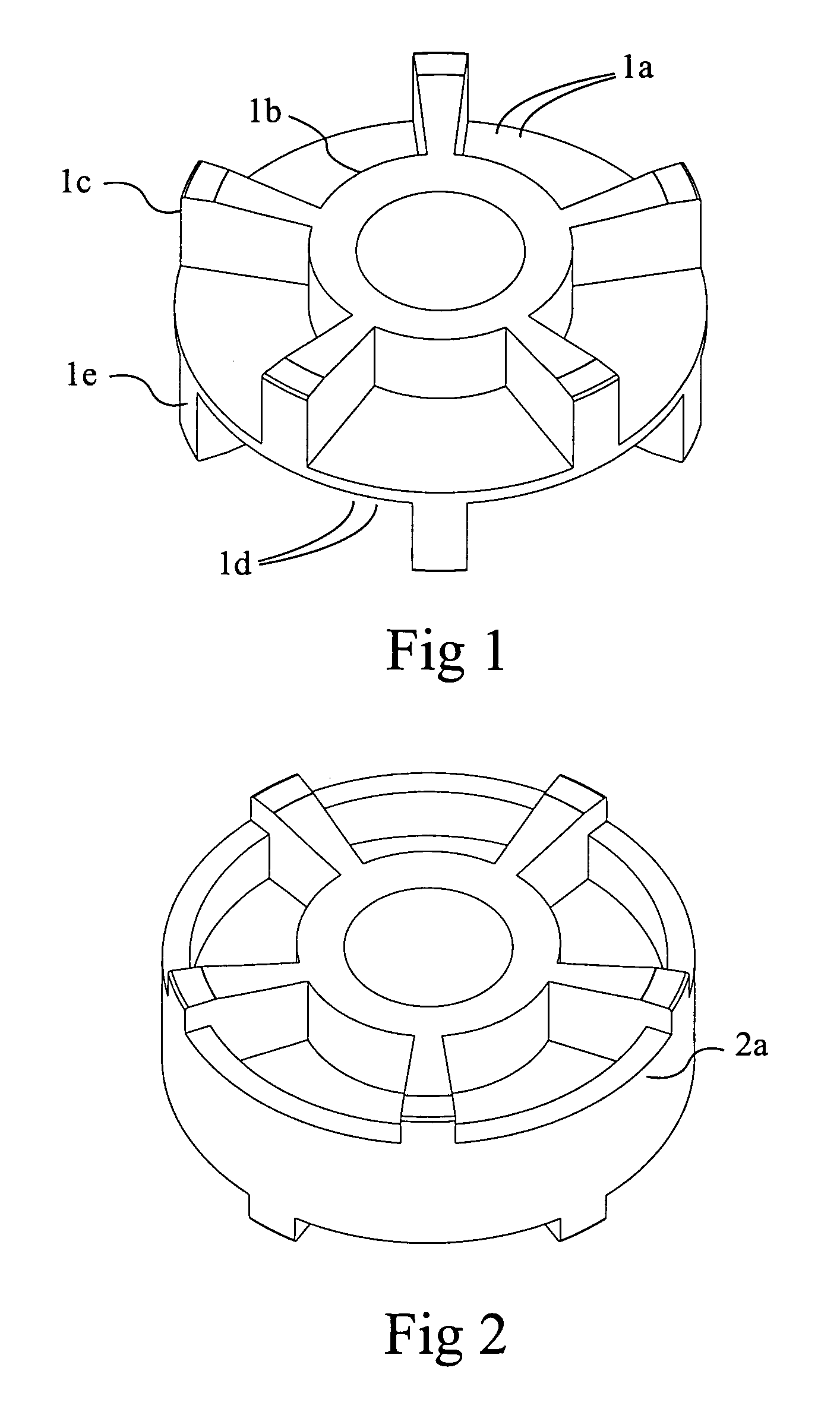
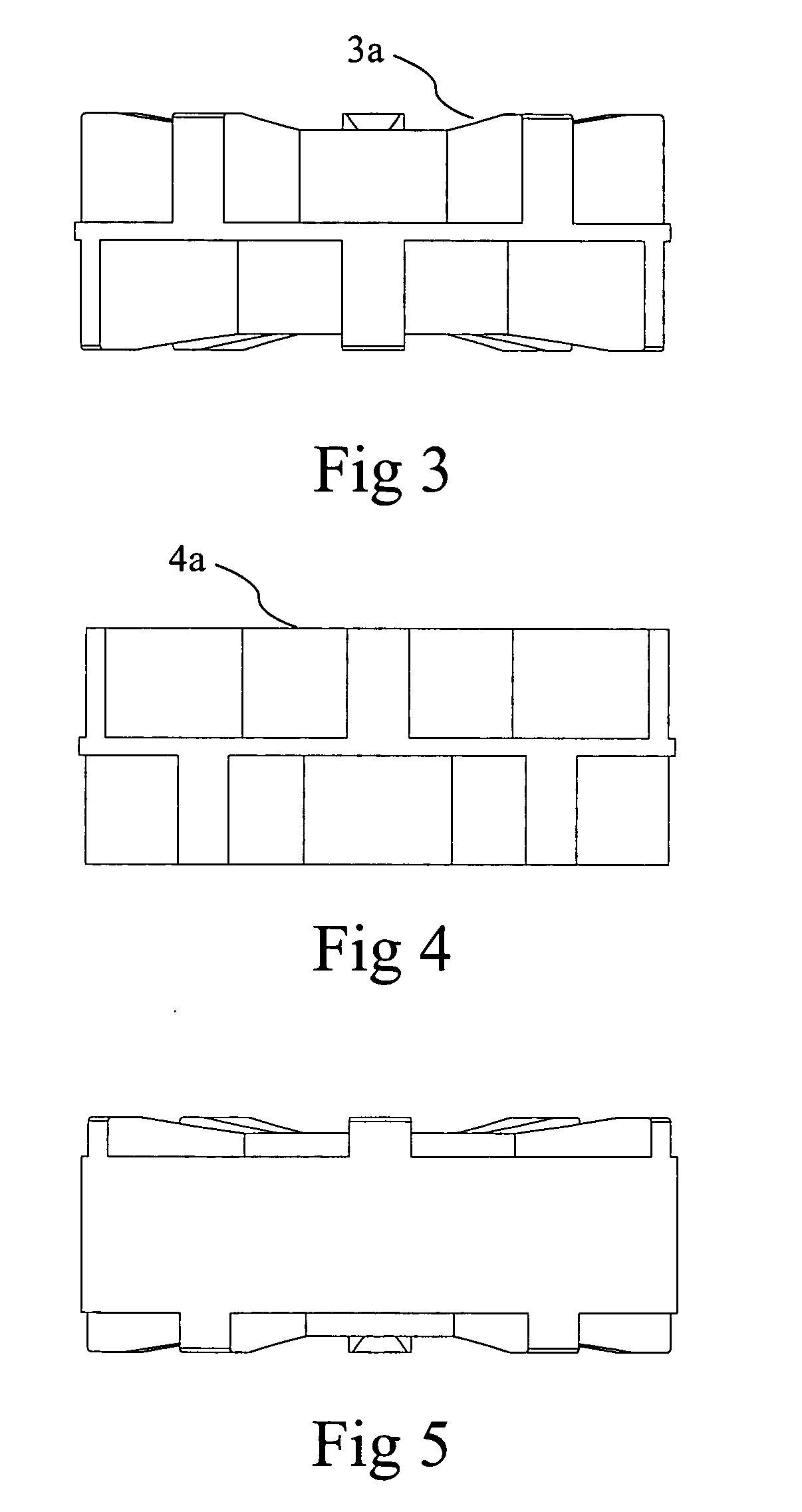
[0018] A washer for use in the mounting of cymbals that consists of a flat washer body FIG. 1a with sleeve 1b extending from the center of the washer and a plurality of ribs 1c that are raised perpendicularly from the washer surface 1a and extend from the sleeve 1b outward to the end of the washer. On the other side of the washer 1d the same amount of ribs 1e are equally formed and positioned to be centrally offset from the first set of ribs.

[0019] In its preferred embodiment this washer is molded out of a thermoplastic elastomer or TPE (i.e. plastic moldable rubber like Santoprene). Also the movement control and sound dampening can be varied with the use of different durometers of elastomer materials.

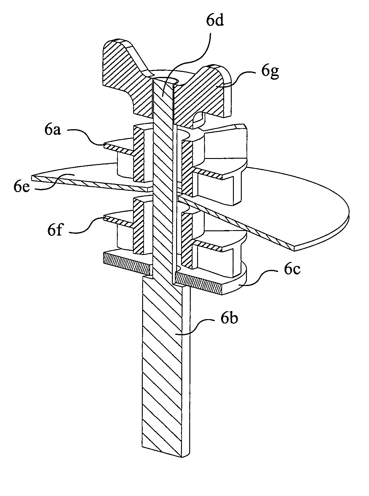
[0020] This washer is installed on a cymbal stand FIG. 6b just like traditional felt based washers. The stand will usually have a platform or washer 6c at the base o...


PUM


Abstract

A resilient washer design having an annulus body and a concentric sleeve extending from the annulus with a plurality of ribs extending from the sleeve. The washer may have an opposing sleeve extending from the opposite side of the annulus with a second plurality of ribs in staggered location to the first set of ribs. This staggered position allows the annulus to flex between the ribs on opposing sides and resist compression of the washer when pressure is applied axially.

Description

CROSS-REFERENCE TO RELATED APPLICATIONS [0001] The present Utility patent application claims priority to the provisional application for patent having the application number of 60 / 644,970 and was filed on Jan. 18, 2005.FIELD OF THE INVENTION [0002] The present invention relates to a novel cymbal washer design that replaces the traditional felt washer providing more stability and control while providing less dampening of the sound. BACKGROUND OF THE INVENTION [0003] Conventionally a metal washer is fitted over the threaded end of the shaft resting on the upper shoulder of the unthreaded portion of the shaft and then a cylindrical plastic sleeve is fitted over the lower end of the threaded portion of the shaft. A felt washer is then slipped over the plastic sleeve, followed by the cymbal which has a circular hole in its center. A second felt washer is then usually placed over the cymbal and a wing nut screwed down upon the upper felt washer to hold the cymbal onto the cymbal stand. Us...

Claims


Application Information

Patent Timeline
Patent Type & Authority Applications(United States)
IPC IPC(8): G10D13/02G10D13/063
CPCG10D13/06G10D13/28G10D13/063
Inventor JUDD, BRIAN THOMAS
Owner NOTTOLI BARRY J
Why Eureka
Try Eureka