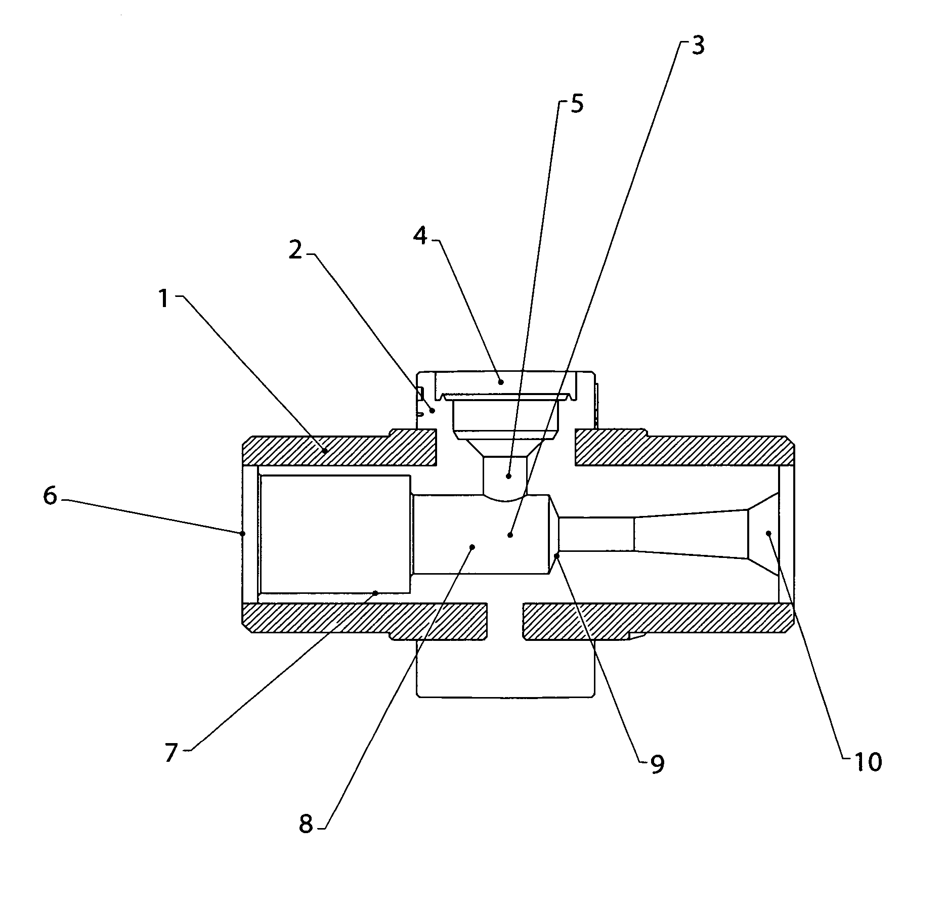
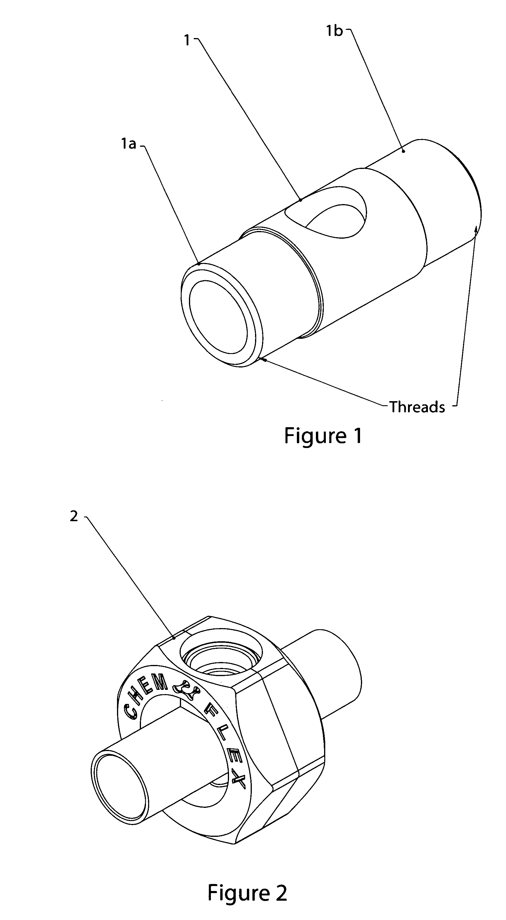
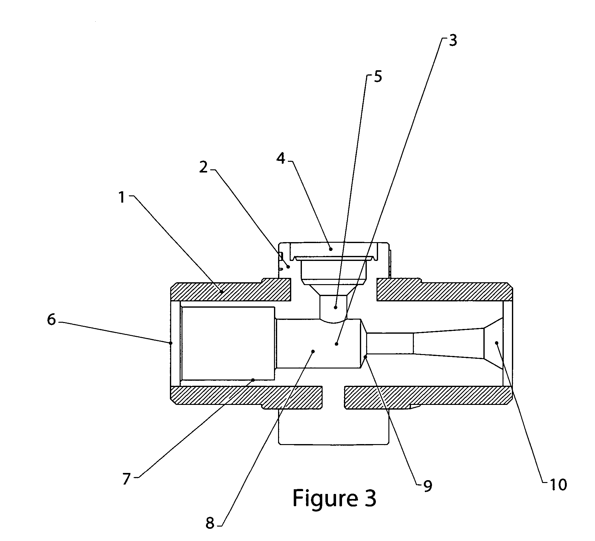
Eductor assembly with dual-material eductor body

Active Publication Date: 2006-07-20
SONNYS HFI HOLDINGS LLC
View PDF11 Cites 22 Cited by
  • Summary
  • Abstract
  • Description
  • Claims
  • Application Information

AI Technical Summary

Benefits of technology

[0004] The present invention combines the strength of a metallic insert with the chemical resistance of an inert molded polymer to form a less expensive eductor housing or body as part of an Eductor Assembly. Primary wetted surfaces in the eductor body are formed from chemically resistant polymer. The complete eductor assembly is comprised of said molded body, a molded nozzle placed inside and coaxially to a molded venturi flow path within the eductor body, and one or two injection assemblies fastened to the eductor body to allow introduction of chemical to the motive flow path. One embodiment incorporates two injection assemblies allowing two separate

Problems solved by technology

While such devices work satisfactorily they are costly to manufacture and have limitations with respect to the flow path geometry.
Some chemical applica

Method used


Image

  • Eductor assembly with dual-material eductor body
  • Eductor assembly with dual-material eductor body
  • Eductor assembly with dual-material eductor body

Examples


Embodiment Construction

[0018] The preferred embodiment will be described in enabling detail in the following text supported by the drawings. The object of this invention is to address all equivalences narrower in scope than the subsequently described invention. In essence this invention is intended to address venturi-style eductors incorporating what is described herein.

[0019]FIGS. 4 and 5 illustrate one embodiment of the present invention wherein a metallic insert as in FIG. 1 is over-molded with an inert polymer having geometry shown in FIG. 2. In this embodiment material used in the molding process is a polyvinylidene fluoride (PVDF) polymer. PVDF is chosen based upon its chemical inertness and strength. Brand names included in the PVDF family include KYNAR and DYFLOR. It is the intent of this invention to include any inert polymer with desirable mechanical properties in the molding process. The metallic insert as depicted in FIG. 1 has machined threads on the outside diameter of an inlet end 1a and a...


PUM


Abstract

An improved venturi-style eductor apparatus for dispensing chemicals into a motive fluid stream where an eductor body FIG. 3 is manufactured by molding a chemically inert polymer material FIG. 2 around and inside a metallic insert FIG. 1. Opposing ends of the metallic insert may be threaded, flanged, or machined for push-in connection to facilitate mating with a motive fluid source and a dispensing device. By manufacturing an eductor assembly using a single-piece metal insert over-molded with an inert polymer provides improved chemical resistance for aggressive applications and allows improvements in venturi geometry not achievable using traditional machined components. This apparatus reduces manufacturing cost over current state-of-the-art eductor assemblies by using a single molding step to create flow-path geometry in the eductor body while retaining mechanical strength with the metallic insert FIG. 1.

Description

BACKGROUND OF THE INVENTION [0001] Venturi-style eductors used to educt a second fluid into a primary motive fluid stream are established fluid handling devices and are used commonly in industrial applications, cleaning applications, and food services. A typical such device may be found in Thompson, U.S. Pat. No. 4,508,272. Common to any such device is an inlet orifice for a motive stream, most often water, where the diameter of the inlet orifice is larger than the smallest diameter in a converging flow-path. Immediately downstream of the converging flow-path is a mixing zone having a diameter larger than the smallest restriction in the converging zone. Transverse to the motive flow path, a port is tapped into an eductor body such that an eduction flow path communicates with the motive flow path at the mixing zone. Bernoulli's equation demonstrates that suction is created in the mixing zone allowing a second solution to be drawn, or educted, into the mixing zone. It is through this ...

Claims


Application Information

Patent Timeline
IPC IPC(8): B01F5/00
CPCB01F5/0413B01F5/0428B01F5/043B01F15/00928Y10T137/87595Y10T137/7036B01F25/31243B01F25/31242B01F25/312B01F35/56
Inventor HARRIS, JAIME LEONARDBROWN, GARY ALLEN
Owner SONNYS HFI HOLDINGS LLC
Why Eureka
Try Eureka