
Vehicle imaging processing system and method

a processing system and vehicle technology, applied in the field of vehicle imaging processing system and method, can solve the problems of image uselessness and imaging difficulties of the whipper blade itself, and achieve the effect of removing the temporary blinding effect of the automotive camera

Inactive Publication Date: 2006-07-20
FORD GLOBAL TECH LLC
View PDF5 Cites 70 Cited by
  • Summary
  • Abstract
  • Description
  • Claims
  • Application Information

AI Technical Summary

Benefits of technology

[0004] The present invention provides an improved vehicle imaging processing system and method which eliminates obstructions or interference from vehicle wiper operation.
[0008] The present invention is advantageous in that it removes the temporary blinding effect of automotive cameras mounted behind the windshield caused by the operation of windshield wipers. Other advantages and features of the present invention will become apparent when viewed in light of the detailed description when taken in conjunction with the attached drawings and appended claims.

Problems solved by technology

At the same time, however, the wiper blades themselves can pose imaging difficulties.
Specifically, the wiper blades temporarily obstruct the camera view and may be interpreted as a detected object in the case of collision avoidance systems, or may render the image useless in the case of a night vision system or other visual aide to the driver.

Method used


Image

  • Vehicle imaging processing system and method
  • Vehicle imaging processing system and method
  • Vehicle imaging processing system and method

Examples


Embodiment Construction

[0017] While the present invention is described with respect to a method and system for image processing for a vehicle imaging system, the present invention may be adapted and utilized in other imaging systems in which one or more image sensors process a scene, including applications outside the field of motor vehicle technology.

[0018] In the following description, various operating parameters and components are described for one constructed embodiment. These specific parameters and components are included as examples and are not meant to be limiting. Also, in the following figures, the same reference numerals will be used to identify the same components.

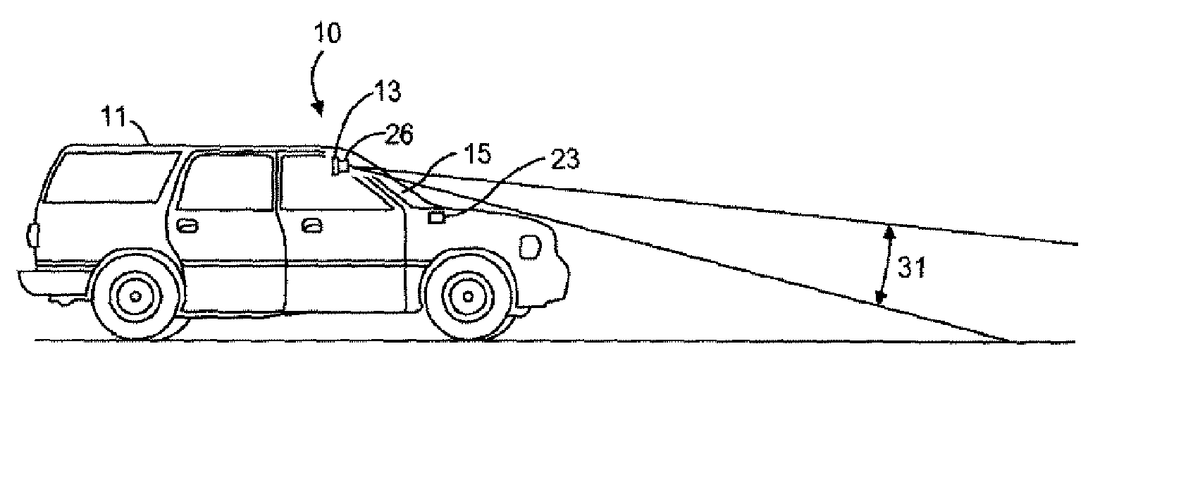
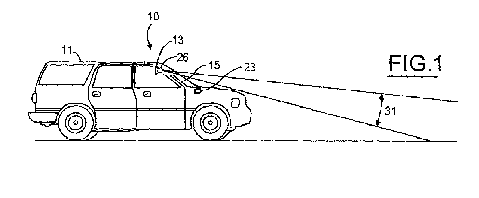
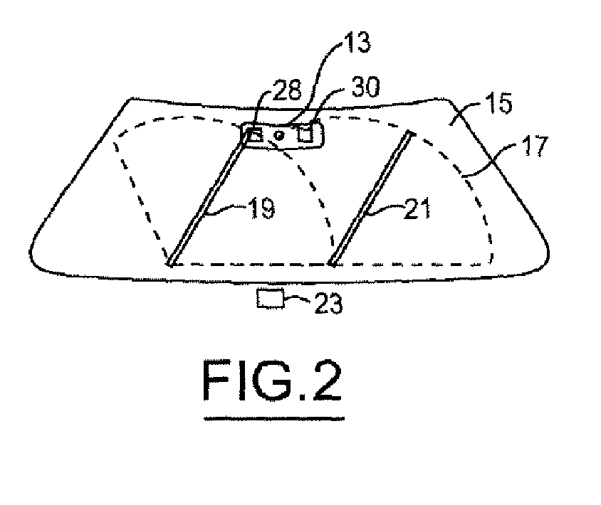
[0019]FIG. 1 shows a side view of a vehicle 11 with an imaging processing system 10 according to one embodiment of the present invention. The imaging processing system 10 includes a vision system 26 which is mounted behind the windshield 15 of the vehicle 11. In this example, as shown in FIG. 2, the vision system 26 includes a ste...


PUM


Abstract

An imaging system for a vehicle is provided. The system includes an image sensor generating a plurality of image frames, and a controller coupled to the image sensor. The controller is programmed to detect an obstructed image frame from the plurality of image frames. The obstruction corresponds to a windshield wiper of the vehicle. In response to detecting an obstructed image, the controller optimizes the obstructed image for display or use by a vehicle system. The controller detects an obstructed image by at least one of object sensing confirmation, edge detection, negative shift detection or headlight illumination detection.

Description

TECHNICAL FIELD [0001] The present invention relates to imaging systems for automotive vehicles, and more particularly, the method and system for eliminating imaging system interference from vehicle wiper systems. BACKGROUND [0002] Remote sensing systems for vehicular applications are becoming more widely known and used. For example, remote sensing systems are known which use radar, lidar, or vision-based technologies for applications such as adaptive cruise control, collision avoidance, collision warning, lane departure, or improved night vision. In applications where cameras are employed, they are commonly configured to be mounted behind the windshield in the interior of the vehicle such that the cameras are protected from outside elements such as weather which may interfere with their ability to detect images. In particular, the cameras are often arranged such that they are within the sweep path of the windshield wipers to provide the best possible clarity for camera imaging. At ...

Claims


Application Information

Patent Timeline
IPC IPC(8): H01L27/00
CPCB60S1/08G06T5/50G06T7/0002
Inventor SHAFFER, ARIC DAVIDMILLER, RONALD HUGH
Owner FORD GLOBAL TECH LLC
Features
  • Generate Ideas
  • Intellectual Property
  • Life Sciences
  • Materials
  • Tech Scout
  • Unparalleled Data Quality
  • Higher Quality Content
  • 60% Fewer Hallucinations
Learn More