
Space division multiplex wireless communication system, device and method for the same

a wireless communication and space division technology, applied in the field of wireless communication systems, can solve the problems of low frequency utilization efficiency, inability to avoid limitation, and easily run short frequency, and achieve the effects of improving frequency utilization efficiency, and improving frequency utilization efficiency

Inactive Publication Date: 2006-07-20
PANASONIC CORP
View PDF6 Cites 21 Cited by
  • Summary
  • Abstract
  • Description
  • Claims
  • Application Information

AI Technical Summary

Benefits of technology

[0018] With this structure, the control unit can orthogonalize the beam patterns of the plurality of base station antenna elements of the base station multi-beam antenna, thereby performing space division wireless point-to-multipoint communications. In particular, frequency utilization efficiency can be improved under environment with few propagation paths.
[0045] According to the present invention, since exchanging received signals can be omitted, it is not necessary to provide circuits for exchanging the received signals in any of the terminals, thereby reducing circuit scales of the terminals.

Problems solved by technology

Therefore, when an available bandwidth is not sufficiently broad, frequency easily runs short.
Regardless of the number of antenna elements of the antennas, this limitation cannot be avoided.
According to the conventional techniques, under environment with few propagation paths, frequency utilization efficiency becomes low.

Method used


Image

  • Space division multiplex wireless communication system, device and method for the same
  • Space division multiplex wireless communication system, device and method for the same
  • Space division multiplex wireless communication system, device and method for the same

Examples


embodiment 1

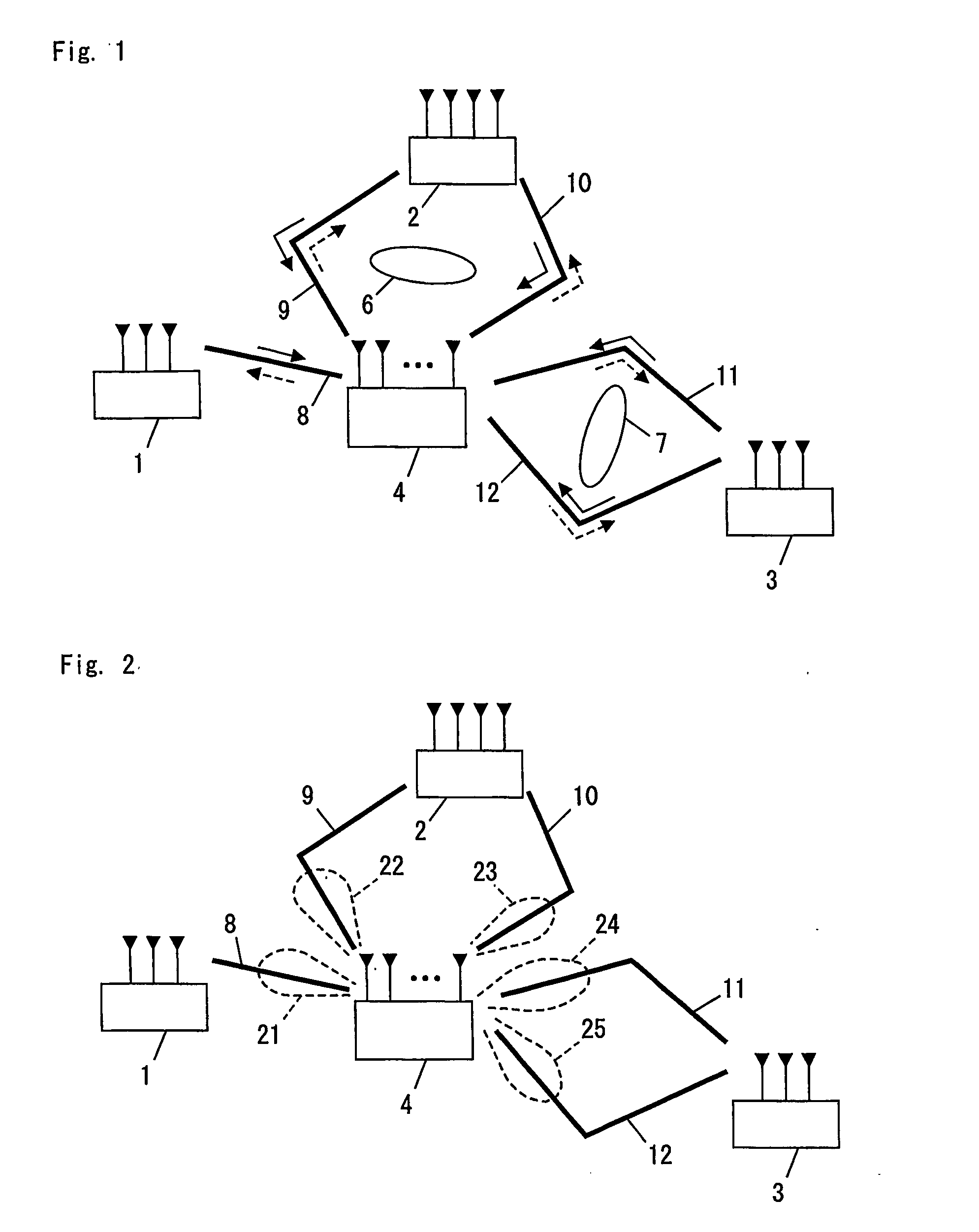
[0065]FIG. 1 is a schematic diagram illustrating a wireless communication system in an embodiment 1 of the present invention. As shown in FIG. 1, the wireless communication system of this embodiment comprises a first terminal 1, a second terminal 2, a third terminal 3, and a base station 4. Outline of the wireless communication system will now be explained in advance of detailed explanation of the base station 4 and each of the terminals 1, 2 and 3.

[0066] In an example of FIG. 1, an electromagnetic-interference object 6 exists between the base station 4 and the second terminal 2, and an electromagnetic-interference object 7 exists between the base station 4 and the third terminal 3.

[0067] Thus, a propagation path 8 is formed between the base station 4 and the first terminal 1. Similarly, a propagation path 9 and a propagation path 10 are formed between the base station 4 and the second terminal 2, and a propagation path 11 and a propagation path 12 are formed between the base stat...


PUM


Abstract

A wireless communication system comprises a base station (4) and terminals (1)-(3). The base station (4) and the terminals (1)-(3) perform a space division multiplex wireless transmission. Each of the base station (4) and the terminals (1)-(3) comprises a multi-beam antenna for a space division multiplex. A beam pattern formed by the multi-beam antenna of the base station (4) is orthogonalized based on transfer function values of a radio-wave-propagation characteristic formed between antenna elements of the multi-beam antenna of the base station (4) and antenna elements of multi-beam antenna of the terminals (1)-(3).

Description

TECHNICAL FIELD [0001] The present invention relates to a wireless communication system that performs space division wireless point-to-multipoint communications using multi-beam antennas and arts related thereto. BACKGROUND ART [0002] Conventionally, a frequency division multiplex (FDM), a time division multiplex (TDM), and a code division multiplex (CDM) are well known. [0003] According to these multiplexing techniques, a plurality of items of information is composed into output data, and the output data is transmitted in a wireless manner. When information multiplicity thereof increases, a necessary radio frequency bandwidth becomes very wide. Therefore, when an available bandwidth is not sufficiently broad, frequency easily runs short. [0004] According to a space division multiplex (SDM), each of a transmitting terminal and a receiving terminal is provided with a plurality of antennas elements, and transmitted data is multiplexed using the same frequency without increasing a radi...

Claims


Application Information

Patent Timeline
IPC IPC(8): H04B7/216
CPCH04B7/0667
Inventor KOGA, SHOUICHIKONDO, JUNJI
Owner PANASONIC CORP
Learn More