
Protective cover for arterial needle

Inactive Publication Date: 2006-07-20
WILLIS ALLAN F +1
View PDF5 Cites 26 Cited by
  • Summary
  • Abstract
  • Description
  • Claims
  • Application Information

AI Technical Summary

Benefits of technology

[0006] It is the object of the present invention to provide a protective cover for an arterial needle which provides an efficient and effective enclosure of the needle tip.
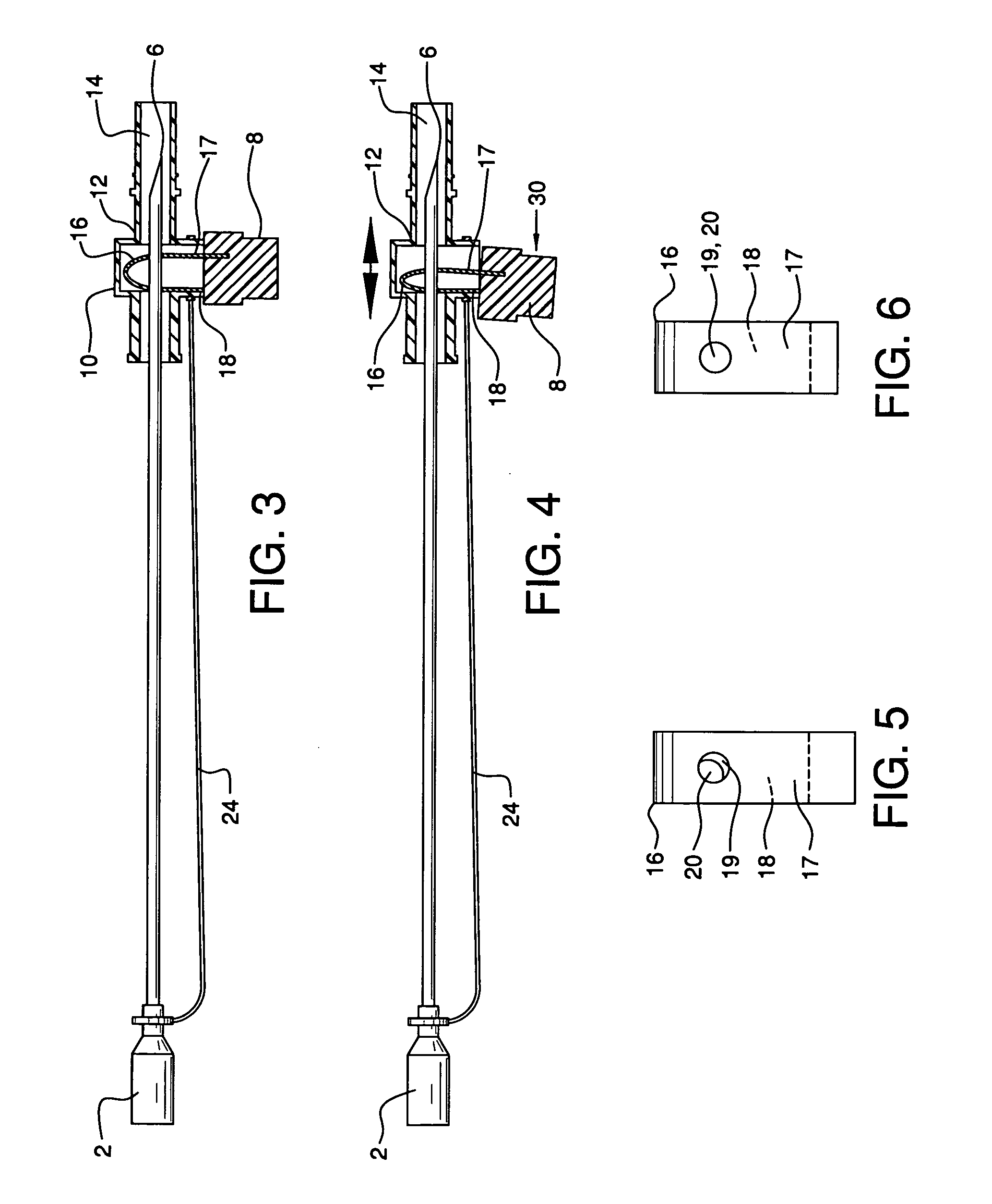
[0014] These and other objects are accomplished by the present invention, a protective cover for arterial needles which is effective in covering the needle tip, but which also can be retracted along the needle shaft to uncover and reopen the needle without interference with the cover or causing contact damage between the cover and the needle tip. The cover has a sheath section with a through channel into which the shaft is slideably received. The cover's sheath section travels substantially along the shaft. This movement is controlled by an actuator control knob connected to a biased locking spring clip or leaf spring located within the sheath section. The locking spring has dual openings through which the shaft travels. When the cover is secured in position on the needle shaft, e.g. when the needle is to be used or when the needle tip is enclosed, the openings are slightly misaligned. This causes locking of the resilient shaft within the protective cover. Pressing the control knob aligns the openings, which unlocks the needle tip and allows the cover to be slid along the shaft.

Problems solved by technology

Of course, it is the extremely sharp tip of the needle which creates a puncture hazard; but if the needle has been contaminated and the skin is pricked or even touched, there is also a real risk of exposure to disease, especially when dealing with highly contagious diseases such as AIDS and hepatitis.
This risk of contamination is especially present during the disposal of needles.
Yet once a cover encloses a tip, it cannot or is not designed to be removed and the needle must be discarded—compelling the use of another needle.

Method used


Image

  • Protective cover for arterial needle
  • Protective cover for arterial needle
  • Protective cover for arterial needle

Examples


Embodiment Construction

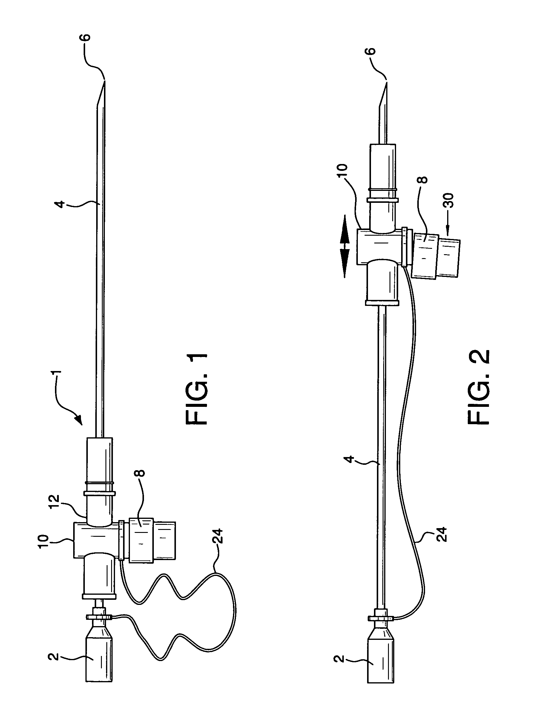
[0022] Arterial needle 1 comprises base member 2 and needle shaft 4 with needle tip 6. Cover 10 is configured to be slideably mounted on shaft 4. Cover 10 has a sheath section 12 with through channel 14 extending therethrough. Sheath section 12 further comprises outwardly extending actuator control knob 8 connected to biased locking spring, spring clip or leaf spring 16. Locking spring 16 has two legs 17 and 18 and dual openings 19 and 20. Opening 19 extends through leg 17 and opening 20 extends through leg 18. Openings 19 and 20 are slightly misaligned, in the normal biased position of locking spring 16, as seen in FIG. 5. When a compressive force is applied to locking spring 16, openings 19 and 20 become aligned as seen in FIG. 6. The lower end of leg 18 provides the connection between locking spring 16 and control knob 8.

[0023] When needle 1 is being used, cover 10 is positioned adjacent to base member 2, as seen in FIG. 1. Needle shaft 4 extends through channel 14 of sheath sec...


PUM


Abstract

A protective cover is provided which is effective in covering the needle tip, but which also can be retracted along the needle shaft to uncover and reopen the needle without interference with the cover or causing contact damage between the cover and the needle tip. The cover has a sheath section with a through channel into which the shaft is slideably received. The cover's sheath section travels substantially along the shaft. This movement is controlled by an actuator control knob connected to a biased locking spring clip or leaf spring located within the sheath section. The locking spring has dual openings through which the shaft travels. When the cover is secured in position on the needle shaft, e.g. when the needle is to be used or when the needle tip is enclosed, the openings are slightly misaligned. This causes locking of the resilient shaft within the protective cover. Pressing the control knob aligns the openings, which unlocks the needle tip and allows the cover to be slid along the shaft.

Description

BACKGROUND OF THE INVENTION [0001] The need to ensure that medical needles, including arterial needles, are properly sheathed when not in use is of critical importance in the healthcare industry. It is necessary that provision is made to safely handle needles both as they are being used and afterward, during the disposal process. Of course, it is the extremely sharp tip of the needle which creates a puncture hazard; but if the needle has been contaminated and the skin is pricked or even touched, there is also a real risk of exposure to disease, especially when dealing with highly contagious diseases such as AIDS and hepatitis. This risk of contamination is especially present during the disposal of needles. [0002] To address this hazardous situation, the medical appliance industry has developed protective covers or guards which are designed to be positioned over the sharp tips of needle shafts. Immediately after a needle is used, a protective cover is placed over the tip, before the ...

Claims


Application Information

Patent Timeline
IPC IPC(8): A61M5/00
CPCA61M5/3275A61M2005/3247
Inventor WILLIS, ALLAN F.CHA, SEDO
Owner WILLIS ALLAN F
Learn More