
Expansion seal

Active Publication Date: 2007-06-07
HRST
View PDF9 Cites 2 Cited by
  • Summary
  • Abstract
  • Description
  • Claims
  • Application Information

AI Technical Summary

Benefits of technology

[0007] Accordingly, the invention presents a hot gas seal that is effective, efficiently designed and durable. The seal does not require flexible metal, fabric or rubber and is not attached to the penetrating conduit. The present invention provides for improved elements thereof in an arrangement for the purposes described that are inexpensive, dependable and fully effective in accomplishing their intended purposes.

Problems solved by technology

This movement plays havoc with the hot gas seals installed on the conduit and casing, eventually causing the seals to fail.
Seal failure may require shutdown and replacement, thereby creating downtime, a safety hazard due to leaking gases at very high temperatures and economic losses due to escape of the working fluid.
The seal failure is especially pernicious if the lateral movement of the conduit is greater than 2 inches.
Currently available commercial seals typically do not accommodate more than 2 inches of lateral movement due to space limitations.
In the related art, this has resulted in seals that are excessively long and / or wide.

Method used


Image

  • Expansion seal
  • Expansion seal
  • Expansion seal

Examples


Embodiment Construction

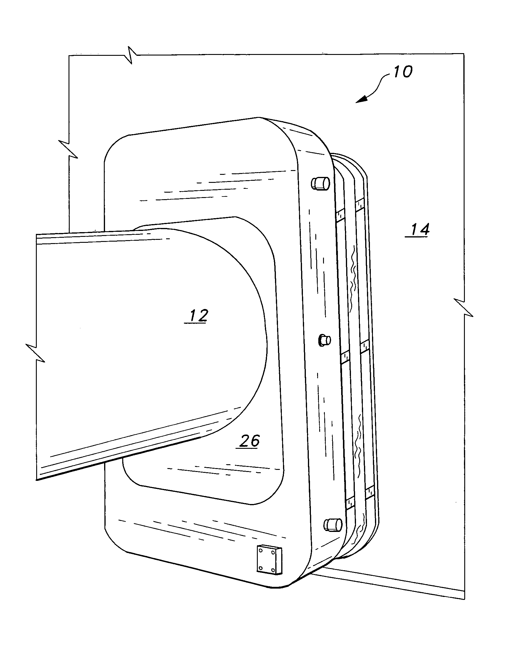
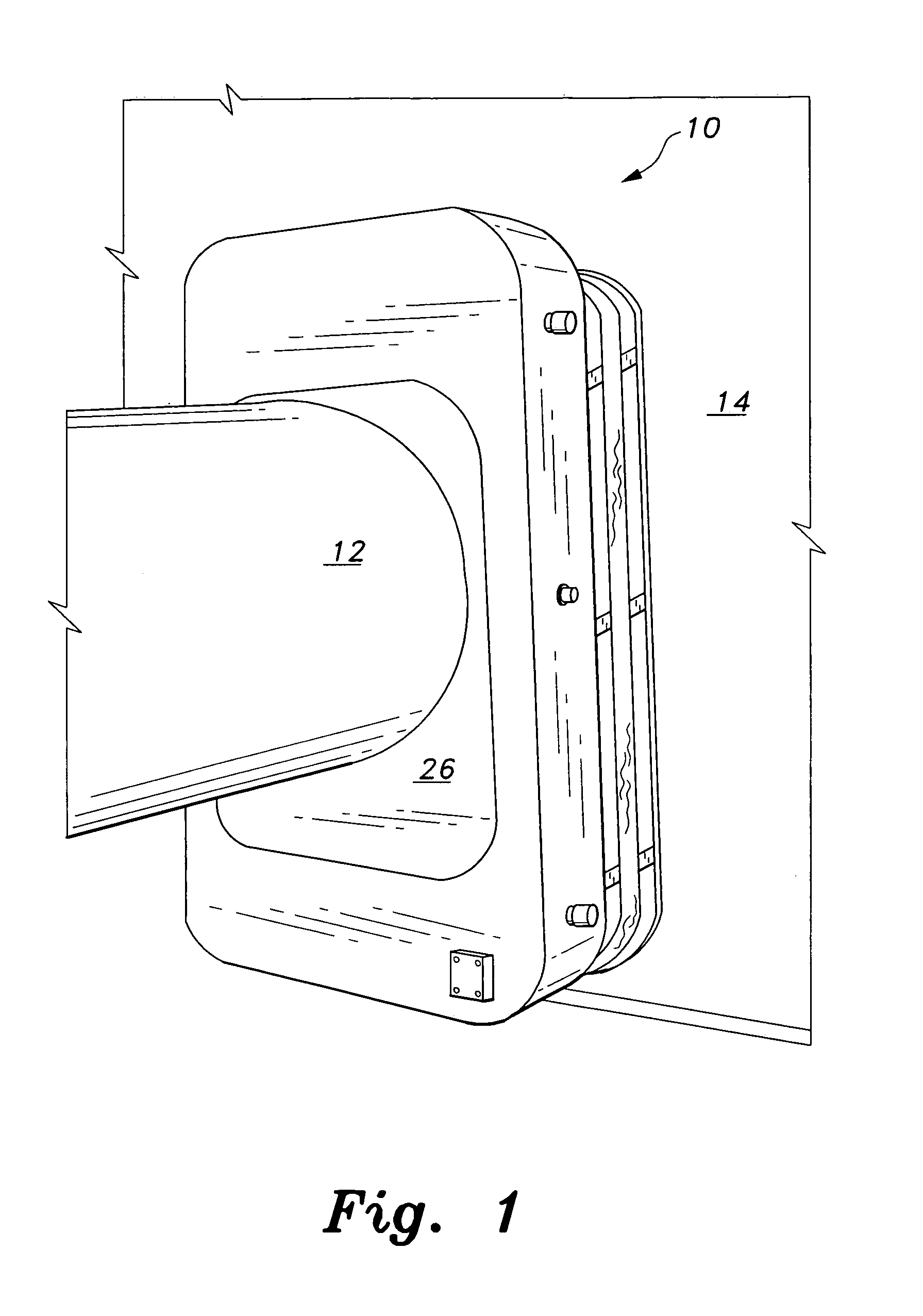
[0019] Attention is first directed to FIGS. 1 wherein the seal of the present invention is generally indicated at 10 and is installed on a horizontal conduit 12, which conduit penetrates the casing 14 of a heat recovery steam generator. The seal 10 is welded in place on casing 14. Although illustrated as employed on a horizontal conduit, it is contemplated that the seal of the present invention can be utilized on lines oriented at other angles and on expansion objects other than fluid-carrying lines.

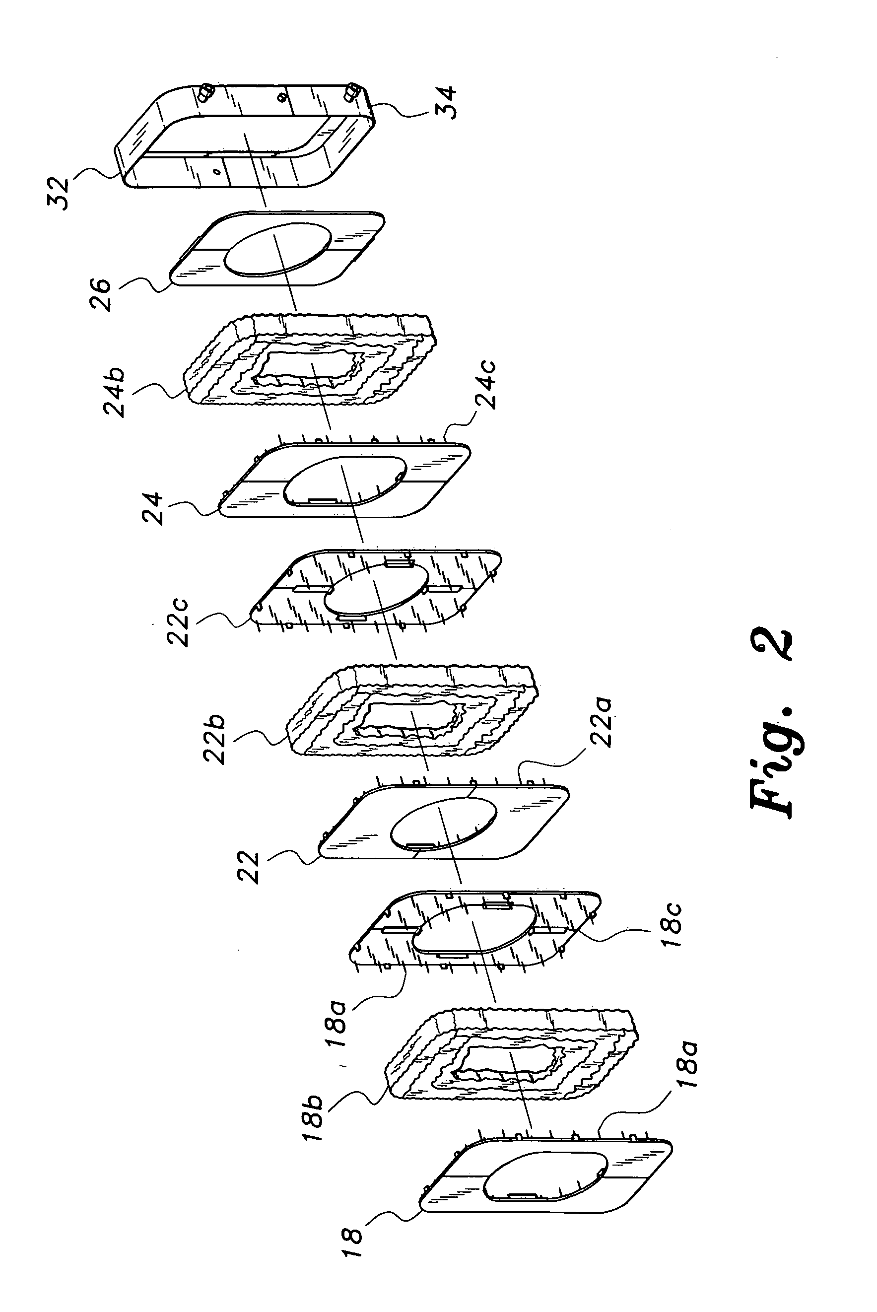
[0020] The schematic illustrated in FIG. 2 shows the serial arrangement of the three, independent, insulation pillows of seal 10. The first or casing pillow comprises a first sheet 18, insulation material 18b and a second cover sheet 18c. Metal pins 18a, welded on the front face of sheet 18 and the rear face of cover sheet 18c, function to hold insulation material 18b in place. When installed, the casing pillow will abut the pressure vessel casing 14. The middle pillow or traveling pill...


PUM


Abstract

A hot gas seal for a conduits penetrating the wall(s) of a vessel such as a heat recovery steam generator unit. The seal will permit lateral movement greater than 2 inches (typically 2″ to 10″) and unlimited axial movement without seal degradation and failure. The instant seal has a life expectancy of at least ten years. The seal includes three serially-arranged, independent insulation segments or pillows. The pillow adjacent the vessel casing and the center pillow employ metal sheets to sandwich insulation therebetween. The center pillow travels laterally with the conduit. The third or outer pillow terminates in a split seal ring having containment structure attached thereto.

Description

BACKGROUND OF THE INVENTION [0001] 1. Field of the Invention [0002] The present invention generally relates to sealing devices. More specifically, the present invention is drawn to a hot gas seal for a conduit or the like, which conduit is inserted in a wall of a heat recovery steam generator or the like. [0003] 2. Description of the Related Art [0004] Large diameter conduits are utilized to effectively and efficiently transport fluids (gases or liquids) to and from pressure vessels such as heat recovery steam generators. These large conduits must penetrate the walls of the pressure vessel and enter the vessel through a gap formed through the casing of the vessel. Usually, because of thermal expansion and contraction, the conduits are subject to lateral and axial movement. This movement plays havoc with the hot gas seals installed on the conduit and casing, eventually causing the seals to fail. Seal failure may require shutdown and replacement, thereby creating downtime, a safety ha...

Claims


Application Information

Patent Timeline
IPC IPC(8): F16L41/00
CPCF16L5/10
Inventor KROWECH, ROBERT J.NAGEL, DARRYL M.YAEGER, DOUGLASS R.
Owner HRST
Learn More