Pedicle screw systems and methods of assembling/installing the same

a technology of pedicle screw and screw body, which is applied in the field of pedicle screw assembly, can solve the problems of more tissue damage in and around the surgical site, lack of features that enhance and/or benefit newer techniques, and art pedicles

Inactive Publication Date: 2006-07-20
ALPINESPINE
View PDF13 Cites 192 Cited by
  • Summary
  • Abstract
  • Description
  • Claims
  • Application Information

AI Technical Summary

Benefits of technology

[0013] The embodiments described herein are generally related to a bone fixation assembly or pedicle screw system for the internal fixation of vertebral bodies. The pedicle screw system may be used to fix, correct, stabilize, and / or reinforce spinal segments, among other things and may be particularly advantageous when minimally invasive surgery (MIS) techniques are employed. The pedicle screw system includes a tulip assembly comprising a tulip body, a inner member, an expansion member, and a cap assembly. Installation of the pedicle screw system into pedicles of the spine, for example, includes inserting the pedicle screw into a portion of the spine, coupling a partial assembly comprising the tulip body, inner member, and expansion member to the pedicle screw, placing a rod in the inner member, and then coupling the cap assembly to the tulip body. The partial assembly may be locked onto the pedicle screw before or after placement of the rod. In addition, the cap assembly operates to further lock the tulip assembly to the pedicle screw and to capture and lock the rod with the tulip assembly.

Problems solved by technology

Although conventional prior art pedicle screw systems exist, they lack features that enhance and / or benefit newer, minimally invasive surgery (MIS) techniques that are more commonly being used for spinal surgeries.
Some of these pedicle screw systems are rather large and bulky, which may result in more tissue damage in and around the surgical site when the pedicle screw system is installed during surgery.
One drawback that is common among many prior art pedicle screw systems is that a threaded component is used to lock down the rod in the rod-receiving device.
One problem associated with the above-identified pedicle screw systems is that cross-threading may occur when the fastening element is installed.
Cross-threading may cause the fastening element to jam and / or may result in an improper construct where some components may not be in the correct position.
Due to the dynamic nature of spinal movement, a cross-threaded pedicle screw system may be more prone to post-operative failure.
Another problem with the above-identified pedicle screw systems is that the coupling between the fastening element and the rod-receiving device when subjected to dynamic, post-operative loading may result in the walls of the rod-receiving device splaying apart.
In the above-identified pedicle screw systems, the walls of the rod-receiving device are unsupported.
Post-operative tulip splaying, as it is commonly called, may result in the dislodgment of the fastening element and the rod.
In short, the pedicle screw system may become post-operatively disassembled and no longer function according to its intended purpose.
However, the risk and / or potential for cross-threading is still present when the threaded, outer cap is coupled with the rod-receiving device.
; and 6,843,791 to Serhan may address some of the aforementioned drawbacks, but each of these pedicle screw systems are pre-operatively assembled, which makes these systems more difficult to install and maneuver in a spinal operation where MIS techniques are used.

Method used


Image

  • Pedicle screw systems and methods of assembling/installing the same
  • Pedicle screw systems and methods of assembling/installing the same
  • Pedicle screw systems and methods of assembling/installing the same

Examples


Embodiment Construction

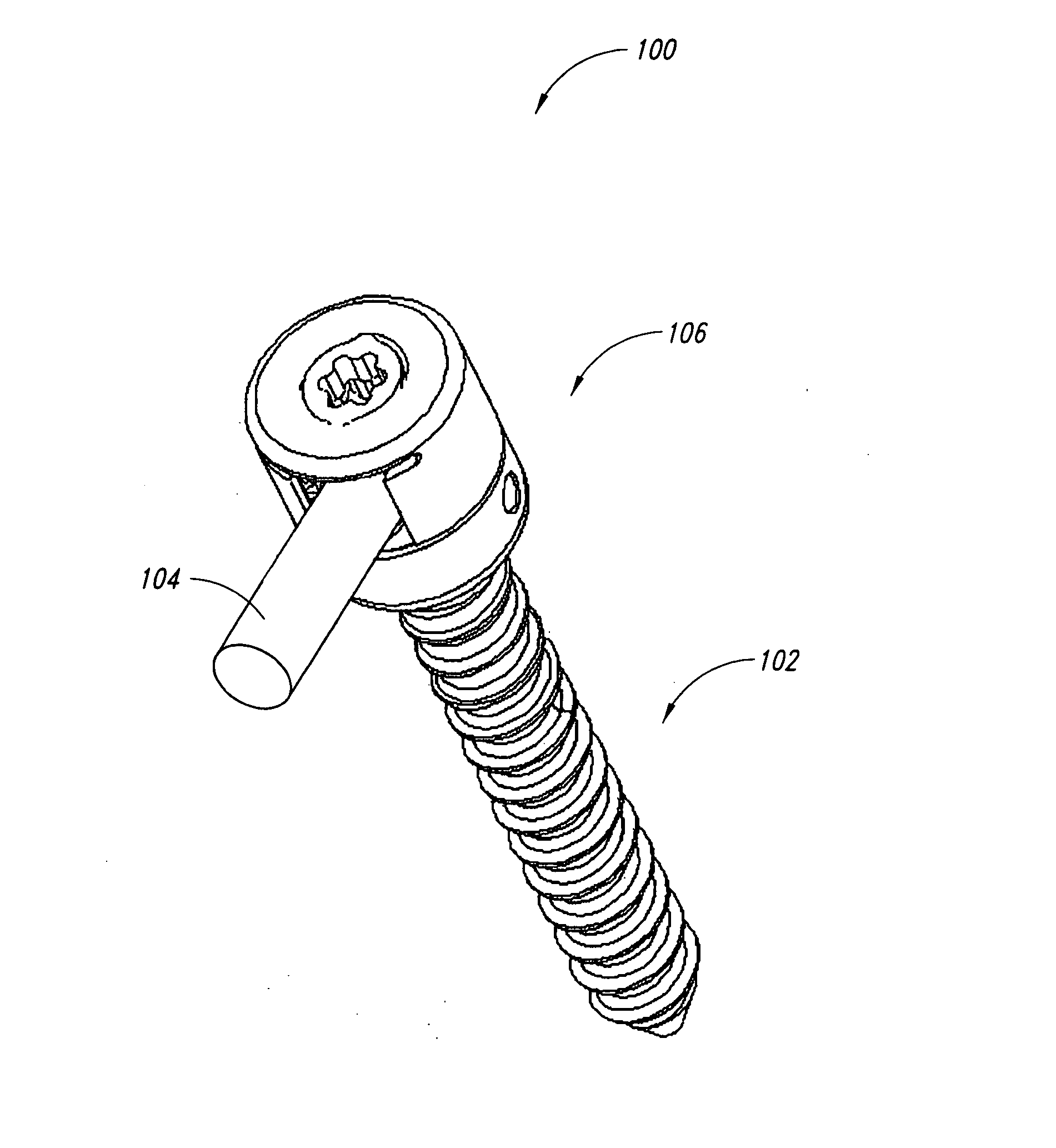
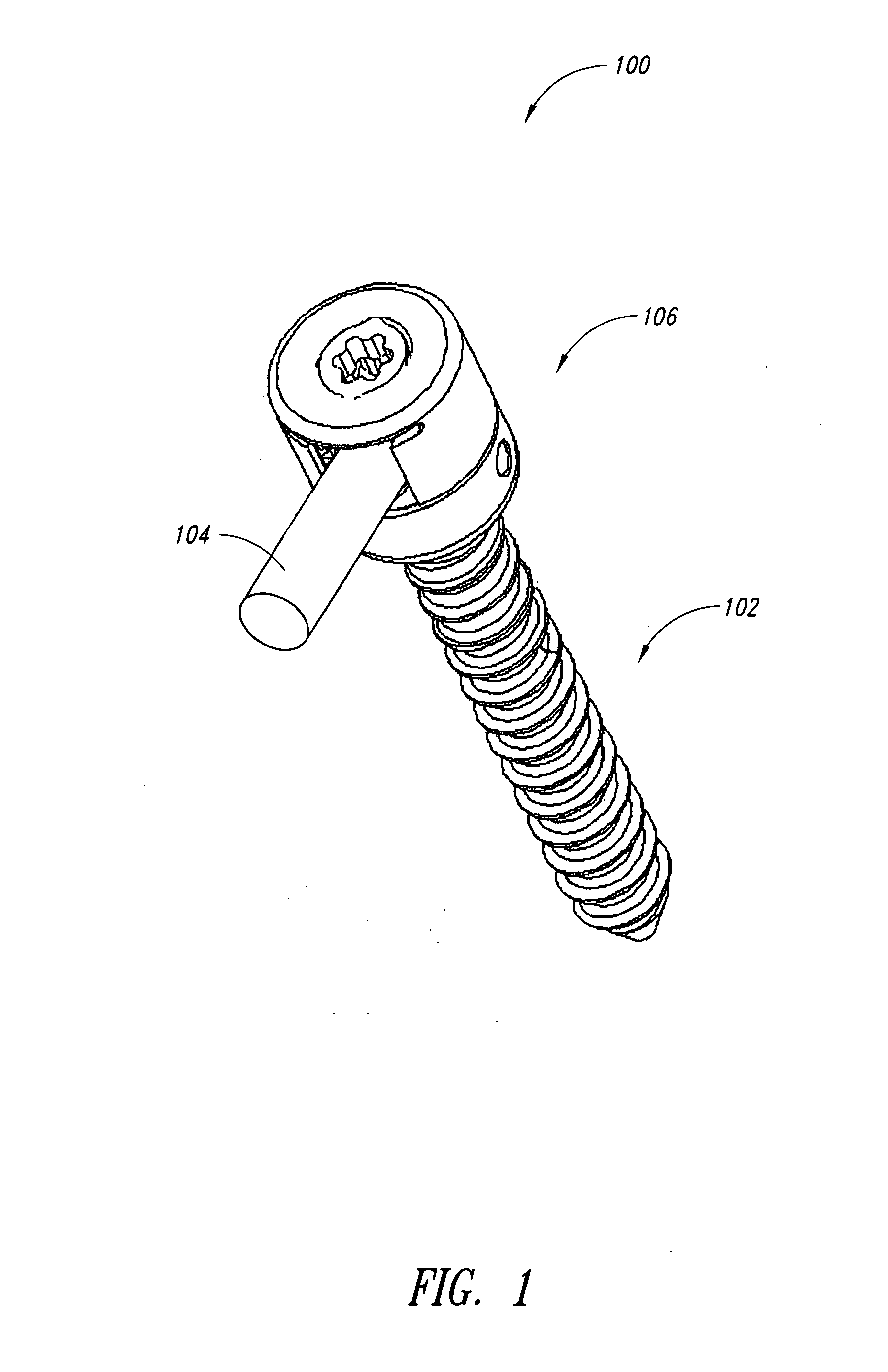
[0027] In one embodiment, pedicle screw systems may be fixed in the spine, for example to perform spinal fixation and / or corrective surgeries, which surgeries may be performed via minimally invasive surgery (MIS) techniques. The systems are inserted into the pedicles of the spine and then interconnected with rods to manipulate (e.g., correct the curvature, compress or expand, and / or structurally augment) at least portions of the spine. Using the MIS approach to spinal fixation and / or correction surgery has been shown to decrease a patient's recovery time and reduce the risks of follow-up surgeries.

[0028] The ability to efficiently perform spinal fixation and / or correction surgeries using MIS techniques is enhanced by the use of pedicle screw systems provided in accordance with the present invention, which systems provide many advantages over conventional systems. For example, a pedicle screw system in accordance with one embodiment provides the advantage that the pedicle screw may ...


PUM


Abstract

The pedicle screw system may be used for fixation of spinal segments and may be advantageous when minimally invasive surgery (MIS) techniques are employed. The pedicle screw system includes a tulip assembly comprising a tulip body, a inner member, an expansion member, and a cap assembly. Installation of the pedicle screw system into pedicles of the spine, for example, includes inserting the pedicle screw into a portion of the spine, coupling a partial assembly comprising the tulip body, inner member, and expansion member to the pedicle screw, placing a rod in the tulip assembly, and then coupling the cap assembly to the tulip body. Coupling the cap assembly to the tulip body includes initially locking the tulip assembly to the pedicle screw and then locking the rod in the tulip assembly.

Description

CROSS-REFERENCES TO RELATED APPLICATIONS [0001] This application claims the benefit under 35 U.S.C. § 119(e) of U.S. Provisional Patent Application Nos. 60 / 622,107 filed Oct. 25, 2004; 60 / 622,180 filed Oct. 25, 2004; and 60 / 629,785 filed Nov. 19, 2004, where these provisional applications are incorporated herein by reference in their entireties.BACKGROUND OF THE INVENTION [0002] 1. Field of the Invention [0003] The present invention relates generally to bone fixation devices, and in particular to a screw assembly for the internal fixation of vertebral bodies. [0004] 2. Description of the Related Art [0005] Various devices for internal fixation of bone segments in the human or animal body are known in the art. One type of system is a pedicle screw system, which is sometimes used as an adjunct to spinal fusion surgery, and which provides a means of gripping a spinal segment. A conventional pedicle screw system comprises a pedicle screw and a rod-receiving device. The pedicle screw inc...

Claims


Application Information

Patent Timeline
Patent Type & Authority Applications(United States)
IPC IPC(8): A61F2/30
CPCA61B17/7032A61B17/7037
Inventor HAWKES, DAVID T.ENSIGN, MICHAEL D.SWEENEY, THOMAS M. IIWARNICK, DAVID R.
Owner ALPINESPINE
Why Eureka
Try Eureka