
Endoscopic stent delivery system and method

a stent and endoscope technology, applied in the field of endoscope stent delivery systems and methods, can solve the problems of excessive friction between the inner assembly of the pellethane jacket, contributing to a hazardous condition for the patient, and affecting the patient's recovery

Inactive Publication Date: 2006-07-20
BOSTON SCI SCIMED INC
View PDF27 Cites 0 Cited by
  • Summary
  • Abstract
  • Description
  • Claims
  • Application Information

AI Technical Summary

Problems solved by technology

However, the multi-layer exterior tube may be stiff and susceptible to kinking and stretching, resulting in damage to the delivery system during a medical procedure, thus possibly creating a hazardous condition for the patient.
This latter design may result in excessive friction between the Pellethane jacket inner assembly and the PTFE exterior tube liner during deployment / reconstrainment in a tortuous anatomy.
The resulting cumulative force can exceed the maximum allowable force requirement for such stent delivery systems, thus possibly resulting in damage to the stent or stent delivery system during a medical procedure and, hence, contributing to a hazardous condition for the patient.
Use of a relatively stiff material for the outer or inner assembly of the stent delivery device may result in kinking or breaking of the assembly, but inhibits stretching of the assembly during deployment / reconstrainment and promotes structural integrity of the assembly.
For example, material with a durometer measure of 75D may be stiff enough to provide structural integrity, but may be too stiff to manipulate around corners or bends.

Method used


Image

  • Endoscopic stent delivery system and method
  • Endoscopic stent delivery system and method
  • Endoscopic stent delivery system and method

Examples


Embodiment Construction

[0002] 1. Field of the Invention

[0003] The present invention relates to stent delivery systems and methods. More particularly, the present invention relates to endoscopic stent delivery systems and methods.

[0004] 2. Background of the Invention

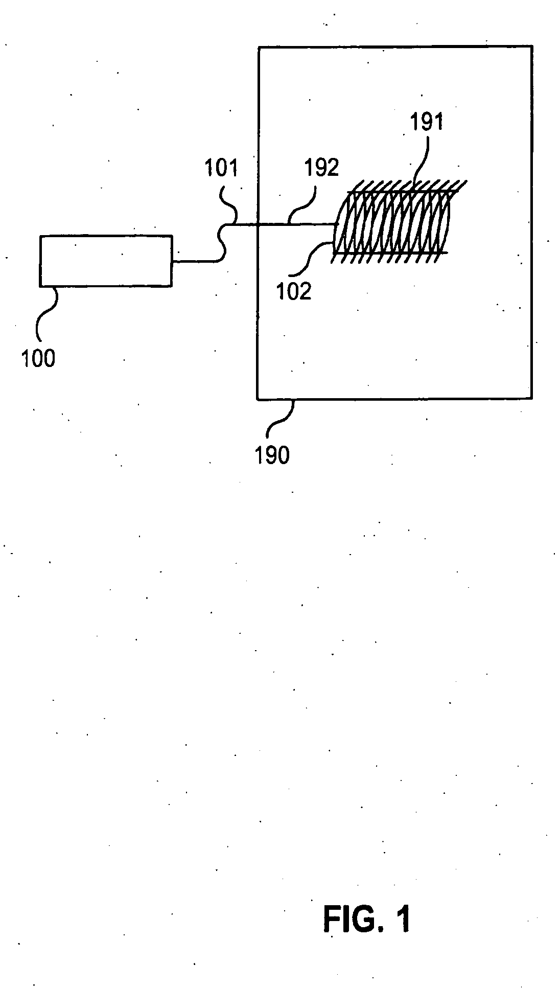
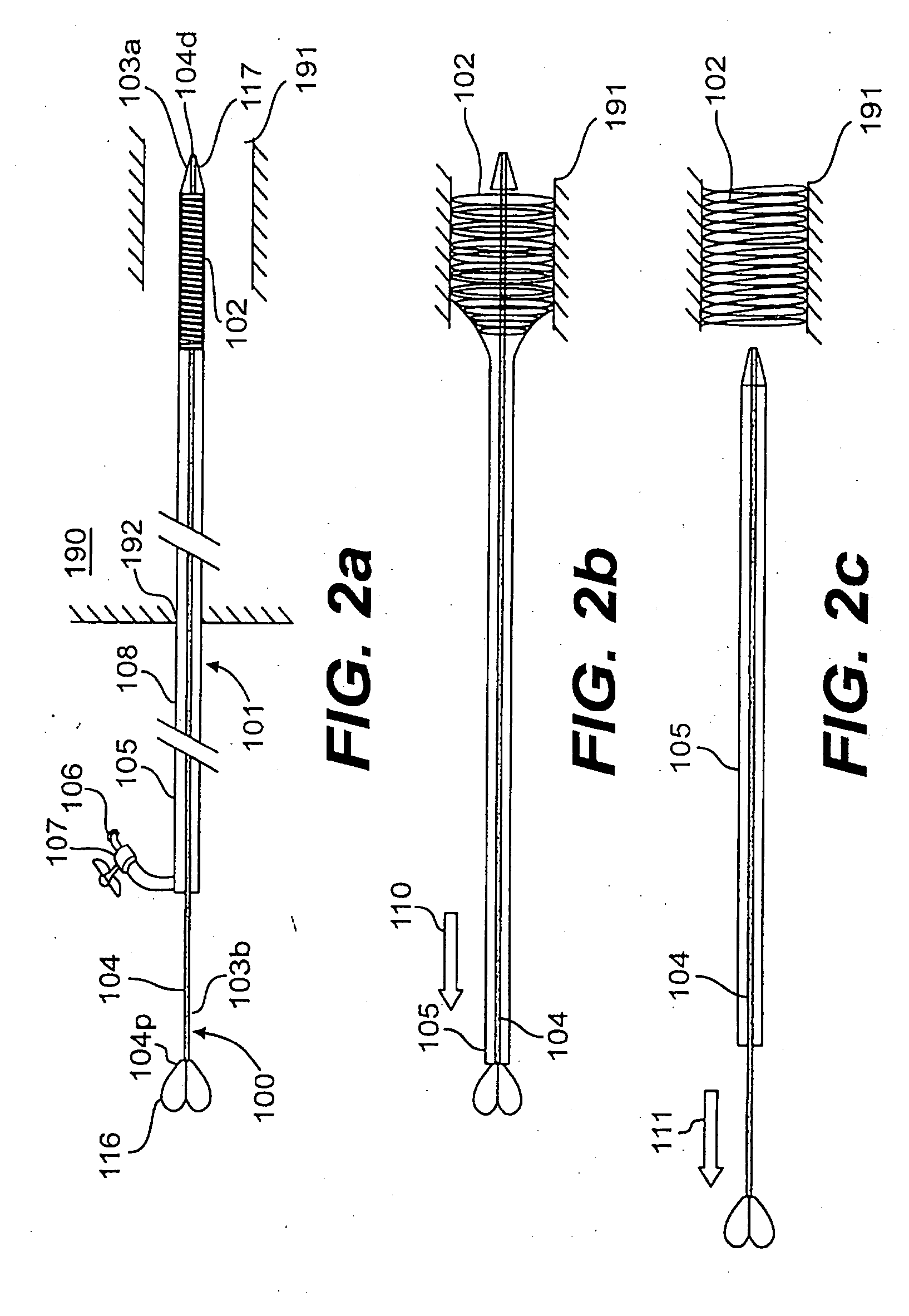
[0005] Medical stents may be used in a variety of medical procedures. Such stents may be used to provide structural support to an anatomical structure, such as a fluid vessel, in order to prevent the structure from collapse, widen the lumens of such structures to reverse an occluded state, or allow other material to be injected or removed through the anatomical structure. Typically, such medical stents are delivered to a target anatomical structure in a tissue system via stent delivery systems. These stent delivery systems may be elongated devices that are through fluid vessels into or in proximity to target organs or tissue systems. Once in position, an outer tubular projection of the stent delivery system is retracted proximally while an i...


PUM


Abstract

A stent delivery system is disclosed that has an outer assembly and an inner assembly that accommodates a stent. The inner assembly further has an external assembly contact area projecting from its surface that frictionally contacts an inner surface of the outer assembly. The contact area is positioned at one end of the inner assembly, proximal to the stent accommodating area. Also disclosed is a method of using the stent delivery system.

Description

CROSS-REFERENCE TO RELATED APPLICATIONS [0001] This is a continuation of U.S. patent application Ser. No. 09 / 843,941, filed Apr. 01, now pending, the entirety of which is incorporated herein by reference.DESCRIPTION OF THE INVENTION [0002] 1. Field of the Invention [0003] The present invention relates to stent delivery systems and methods. More particularly, the present invention relates to endoscopic stent delivery systems and methods. [0004] 2. Background of the Invention [0005] Medical stents may be used in a variety of medical procedures. Such stents may be used to provide structural support to an anatomical structure, such as a fluid vessel, in order to prevent the structure from collapse, widen the lumens of such structures to reverse an occluded state, or allow other material to be injected or removed through the anatomical structure. Typically, such medical stents are delivered to a target anatomical structure in a tissue system via stent delivery systems. These stent delive...

Claims


Application Information

Patent Timeline
Patent Type & Authority Applications(United States)
IPC IPC(8): A61F2/06A61F2/84
CPCA61F2/95A61F2/966
Inventor HEMERICK, JAMES F.SCHNEIDER, ERIC
Owner BOSTON SCI SCIMED INC
Learn More