A kind of ENT endoscope bracket

An endoscope and ENT technology, applied in the field of ENT endoscope brackets, can solve the problems of inconvenient operation, unclear surgical field of view, and hidden dangers of clinical work, etc., so as to reduce the hidden danger of visual field safety and clear the surgical field of view Stable and convenient effect for clinical work

Active Publication Date: 2022-06-21
SZ HUGEMED MED TECH DEV CO LTD
View PDF14 Cites 0 Cited by
  • Summary
  • Abstract
  • Description
  • Claims
  • Application Information

AI Technical Summary

Problems solved by technology

Because one hand of the operator cannot be released and the hand will shake, resulting in unclear surgical field of vision, etc.; it is inconvenient for the operator during operation
Not only increases the burden on patients, but also brings many hidden dangers to clinical work

Method used


Image

  • A kind of ENT endoscope bracket
  • A kind of ENT endoscope bracket
  • A kind of ENT endoscope bracket

Examples


Embodiment 1

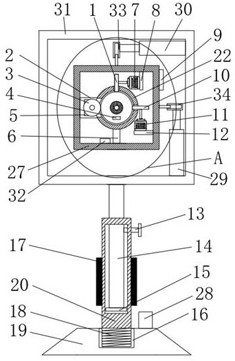
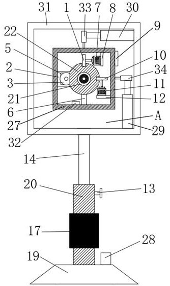
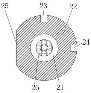
[0023] see Figures 1 to 5 In the embodiment of the present invention, the bottom of the support column 20 is provided with a support device, the support column 20 is connected with a mounting frame 31 through a lifting device, and the mounting frame 31 is connected with a fixed frame 27 through a position adjustment device, and the inner bottom side wall of the fixed frame 27 is connected. A connecting rod 6 is fixedly connected to the top, and a spherical shell 22 is fixedly connected to the upper end of the connecting rod 6. The top side wall, right side wall and left side wall of the spherical shell 22 are respectively provided with a first through hole 23, a second through hole 24 and The third through-hole 25, the first through-hole 23, the second through-hole 24 and the third through-hole 25 are respectively vertical, horizontal and vertical. A rotating ball 21 is provided inside the spherical shell 22, and the rotating ball 21 is provided with a The through hole is arr...

Embodiment 2

[0025] see figure 1 , On the basis of Embodiment 1, the lifting device includes a sliding cavity slot, the sliding cavity slot is opened inside the support column 20, the sliding cavity slot is slidably connected with the moving plate 15, and the side wall of the moving plate 15 is fixedly connected with a sliding rod 14. Bolts 13 are fixedly connected to the side walls of the support column 20. The sliding rod 14 penetrates the top and side walls of the sliding cavity groove. The upper end of the sliding rod 14 is fixedly connected to the side wall of the mounting frame 31. 14 can move up and down to drive the mounting frame 31 up and down, and then tighten the bolt 13 to make the sliding rod 14 fixed.

[0026] see figure 1 , the support device includes a bottom plate 19, the upper side of the bottom plate 19 is provided with a threaded groove 16, the bottom of the support column 20 is provided with an external thread 18, and the bottom of the support column 20 is threaded i...

Embodiment 3

[0028] see figure 1 and Figure 5On the basis of Embodiment 1, the position adjustment device includes a radar signal receiver 28, a vertical telescopic cylinder 29, a horizontal telescopic cylinder 30 and a position signal transmitter 32, and the vertical telescopic cylinder 29 is vertically and fixedly connected to the interior of the installation frame 31. On the bottom side wall, the horizontal telescopic cylinder 30 is fixedly connected horizontally on the side wall of the mounting frame 31, and one end of the vertical telescopic cylinder 29 and the horizontal telescopic cylinder 30 are fixedly connected with a first first fixing pipe 34 and a second fixing pipe 33 respectively. , a first support rod 35 is slidably connected in the first fixing rod 34, one end of the first support rod 35 is fixedly connected to the side wall of the fixing frame 27, and a second support rod 36 is slidably connected inside the second fixing pipe 33, One end of the second support rod 36 is ...


PUM


Abstract

The invention discloses an ear, nose and throat endoscope bracket, which includes a support column, a support device is provided at the bottom of the support column, and the support column is connected with a mounting frame through a lifting device, and the mounting frame is connected with a position adjusting device. A fixed frame, the inner bottom side wall of the fixed frame is fixedly connected with a connecting rod, the upper end of the connecting rod is fixedly connected with a spherical shell, and the top side wall, the right side wall and the left side wall of the spherical shell are respectively provided with The first through hole, the second through hole and the third through hole. The invention is reasonable in design and ingenious in conception. Even if the doctor's hand shakes, the angle and position of the endoscope can be automatically adjusted, so that the surgical field of view is clear and stable, which brings more convenience to clinical work and reduces the hidden danger of visual field safety.

Description

technical field [0001] The invention relates to the technical field of medical equipment, and in particular, to an ENT endoscope bracket. Background technique [0002] The ENT endoscope uses the good lighting of the endoscope to transform the traditional destructive operation into a complete removal of the lesions, preserving the normal structure of the nasal cavity and paranasal sinuses, forming good drainage and ventilation, using the ENT The speculum can maintain the shape and function of the nasal cavity and sinus mucosa. [0003] However, in the prior art, the conventional ENT endoscopic operation is performed by the operator holding the endoscope in the left hand and the surgical instrument in the right hand. Because one hand of the surgeon cannot be liberated and the hand will shake, the surgical field of vision is not clear, etc.; the surgeon is inconvenient during the operation and use. It not only increases the burden on patients, but also brings many hidden dang...

Claims


Application Information

Patent Timeline
Patent Type & Authority Patents(China)
IPC IPC(8): A61B1/00A61B1/05
CPCA61B1/00066A61B1/0016A61B1/00183A61B1/05A61B1/00147
Inventor 靳军平
Owner SZ HUGEMED MED TECH DEV CO LTD
Why Eureka
Try Eureka