Cable management system

a management system and cable technology, applied in the direction of electrical apparatus casings/cabinets/drawers, coupling device connections, instruments, etc., can solve the problems of increasing the overall length of cables, unable to include adequate routing of cables extending from the rear of such electronic equipment, and unable to achieve the effect of facilitating cable passag

Active Publication Date: 2006-07-27
EATON INTELLIGENT POWER LIMITED
View PDF99 Cites 112 Cited by
  • Summary
  • Abstract
  • Description
  • Claims
  • Application Information

AI Technical Summary

Benefits of technology

[0007] In general, a cable management system for routing cable with respect to electronic equipment is disclosed. The cable management system comprises a cable manager adapted to define a cable path. The cable manager comprises a left side comprising a left side wall, a right side comprising a right side wall, and a rear side, which is substantially

Problems solved by technology

Such systems, do not, however, include adequate routing for cables extending from the rear of such electronic equipment.
Although such ports allow limited passage of cables through the rear panel, they have several drawbacks.
First, the ports are small, such that only a limited number of cables can pass through each port.
This may make adding and removing cables

Method used


Image

  • Cable management system
  • Cable management system
  • Cable management system

Examples


Embodiment Construction

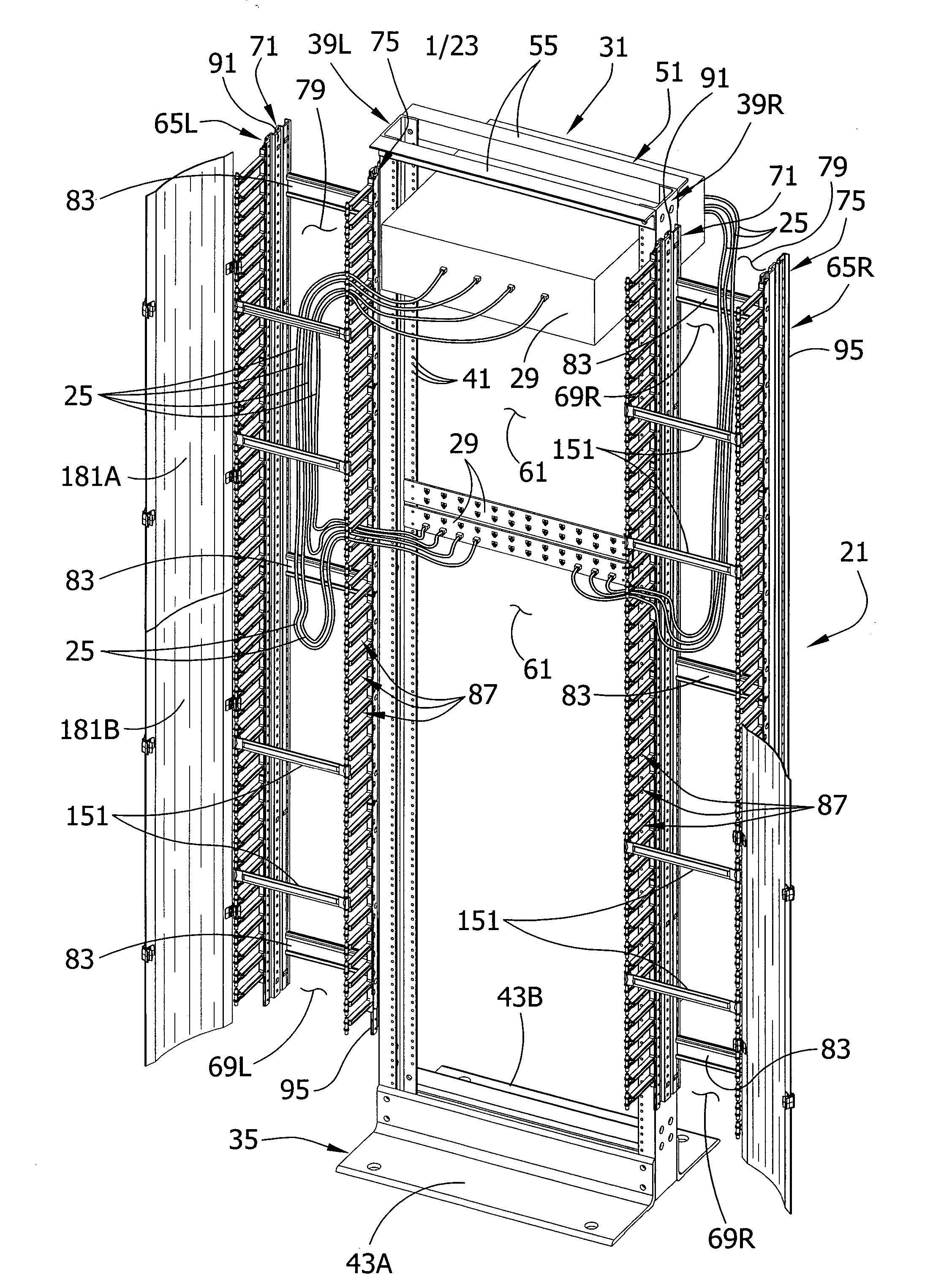
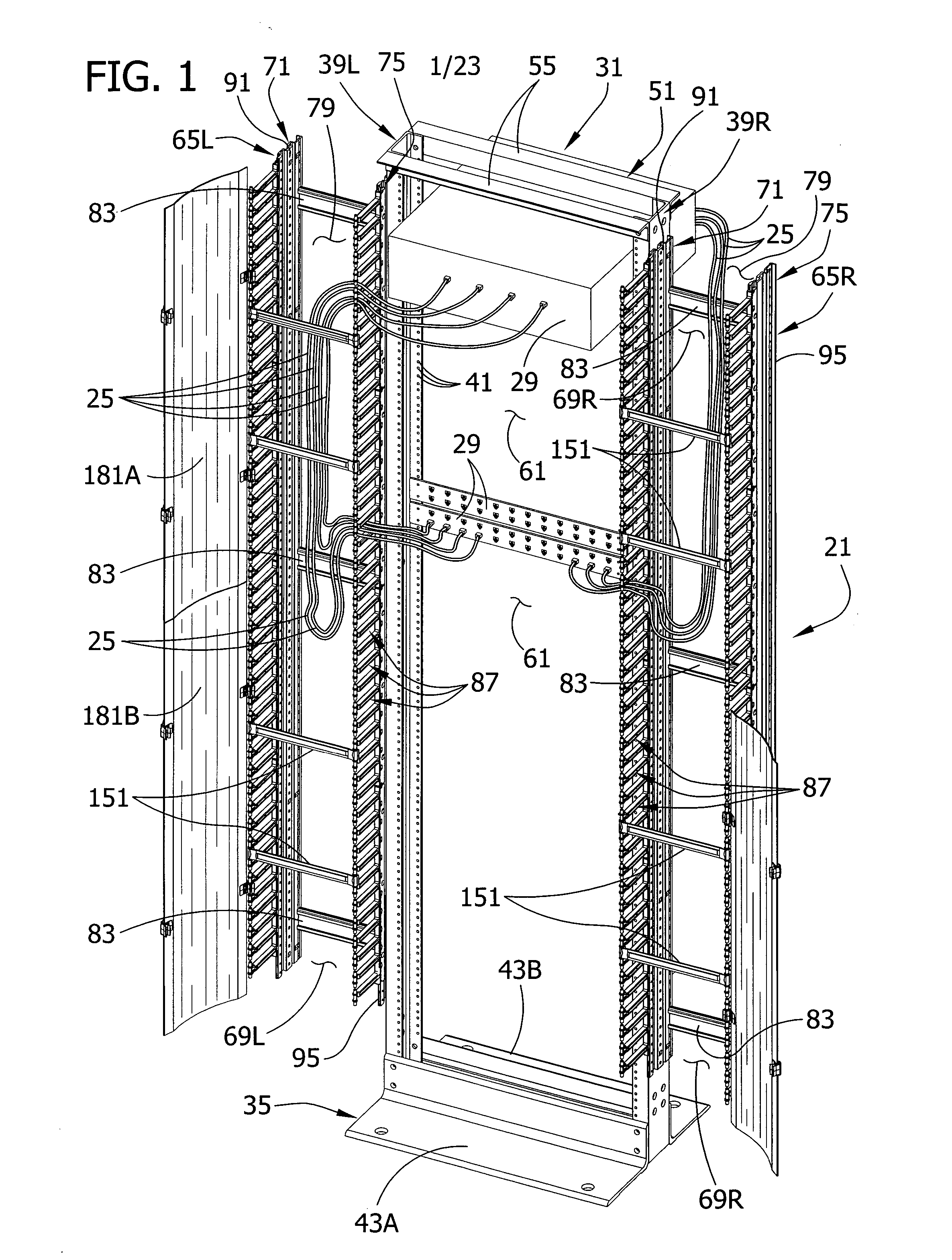
[0043] Referring to FIG. 1 of the drawings, one embodiment of a cable management system of this invention is designated in its entirety by the reference numeral 21. In general, the cable management system 21 routes cable 25 with respect to electronic equipment 29. As described below, this equipment may be mounted on a rack, such as the one generally indicated at 31 in FIG. 1, but it will be understood that the cable management system of this invention can be used without a rack. Electronic equipment 29 may include various types of telecommunications equipment (e.g., patch panels), but it will be readily understood by one skilled in the art that the cable management system is suitable for mounting other types of equipment as well, without departing from the scope of this invention.

Electronic Equipment Rack

[0044] As depicted in FIG. 1, the rack 31 comprises a bottom frame structure, generally designated 35, and at least two uprights, each generally designated 39, secured to the bott...


PUM


Abstract

A cable management system for routing cable with respect to electronic equipment. This system has a variety of improvements providing greater flexibility in routing cable to and from the equipment.

Description

CROSS-REFERENCE TO RELATED APPLICATION [0001] This application claims the benefit of the filing date of U.S. Patent Application Ser. No. 60 / 645,803, filed Jan. 21, 2005. The entire text of the above-referenced application is hereby incorporated herein by reference.BACKGROUND OF THE INVENTION [0002] This invention relates generally to electronic equipment racks, and particularly to cable management systems for such racks adapted to maintain groups of one or more cables separate from one another. [0003] Racks for holding electronic equipment, such as telecommunications equipment, come in various configurations. Some racks, referred to as “two-post” racks, include at least a pair of uprights, one at each side of the rack, extending up from a bottom frame structure. The uprights typically include holes spaced at regular intervals for mounting electronic equipment between the uprights. Such equipment typically includes various types of connectors on both the front and rear of the equipme...

Claims


Application Information

Patent Timeline
IPC IPC(8): H02G3/08
CPCH05K7/186
Inventor RINDERER, ERIC R.NEACE, BRUCE
Owner EATON INTELLIGENT POWER LIMITED
Why Eureka
Try Eureka