Universal serial bus connector with integral shell

Inactive Publication Date: 2006-07-27
HON HAI PRECISION IND CO LTD
View PDF8 Cites 8 Cited by
  • Summary
  • Abstract
  • Description
  • Claims
  • Application Information

AI Technical Summary

Benefits of technology

[0007] It is an object of the present invention to provide a universal serial bus connector with a firm and compact structure.
[0008] In order to attain the objective above, a universal serial bus connector includes a metal casing, an insulative housing and a mating pedestal received in the metal casing, and a printed circuit board with a front portion received in the mating pedestal and a rear portion received in the metal casing. The metal casing integrally forms a mating port and a receiving port. The receiving port defines an opening. The insulative housing includes a planar body and a rear portion. A retaining portion laterally extends from the rear portion and forms a bump for engaging with the opening of the metal casing at a front portion thereof. Since the mating port and the receiving port are integrally formed, the structure of the universal serial bus connector is compact and firm.

Problems solved by technology

However, when the conventional USB drops off accidentally, the bottom cover 1 and the upper cover 2 easily disengage or depart.

Method used


Image

  • Universal serial bus connector with integral shell
  • Universal serial bus connector with integral shell
  • Universal serial bus connector with integral shell

Examples


first embodiment

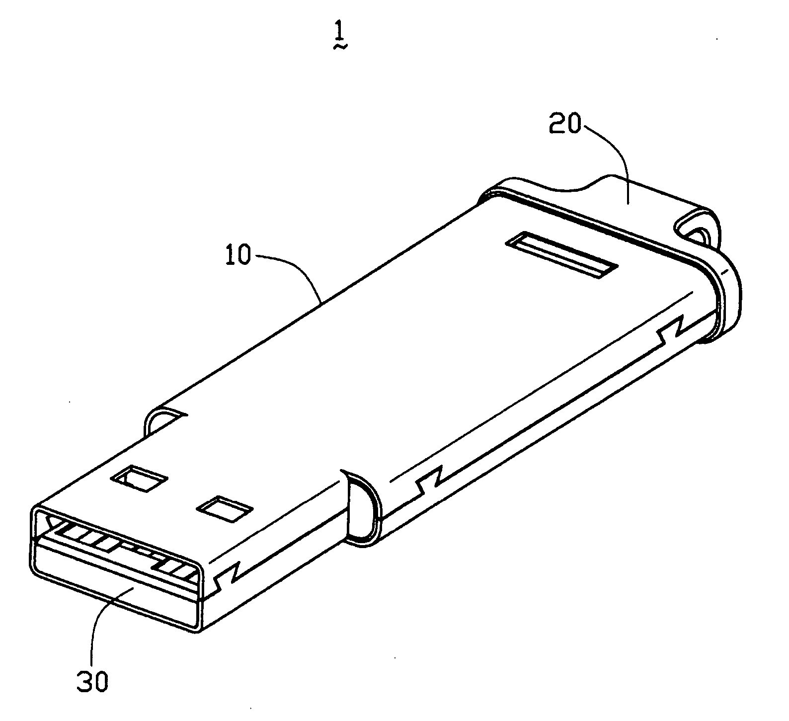
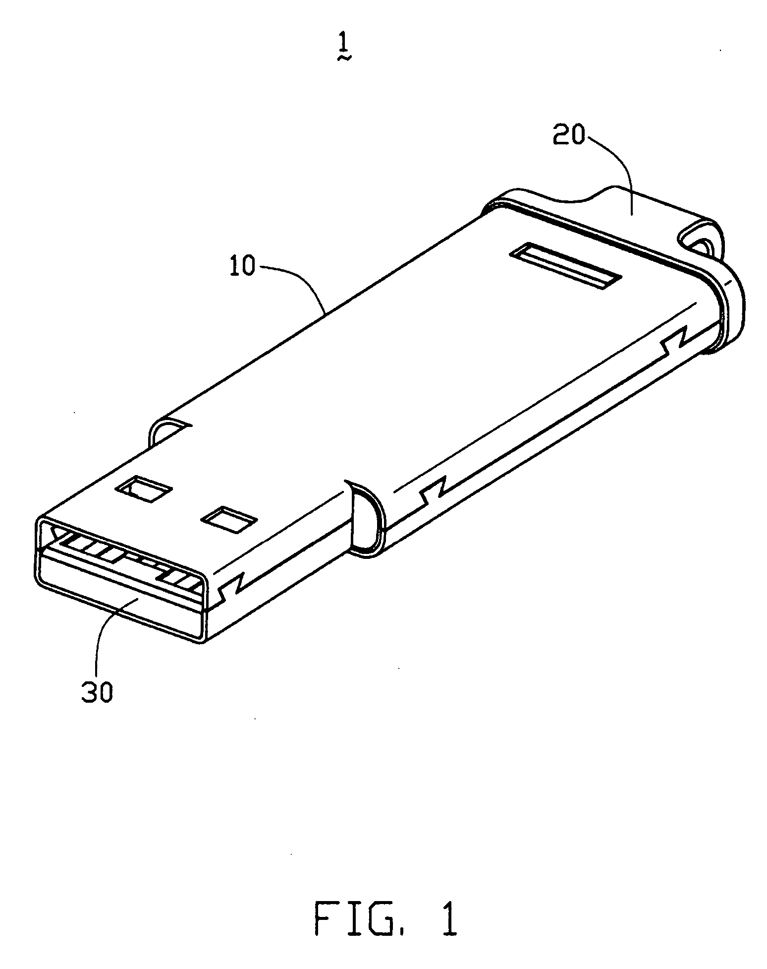
[0018] Refer to FIGS. 1-3, a universal serial bus connector 1 according to the present invention includes a metal casing 10, an insulative housing 20 received in the metal casing 10, a mating pedestal 30 and a printed circuit board 40.

[0019] The metal casing 10 is formed by a top and a bottom metal sheet 11, 12 latched with each other via a plurality of latches 101. The metal casing 10 includes a front mating port 110 for mating with a complementary connector (not shown) and a rear receiving port 120 for receiving the printed circuit board 40 and the insulative housing 20. The top metal sheet 11 defines a rectangular opening 102. The latches 101 are respectively defined in side walls 111 of the mating port 110 and side walls 121 of the receiving port 120.

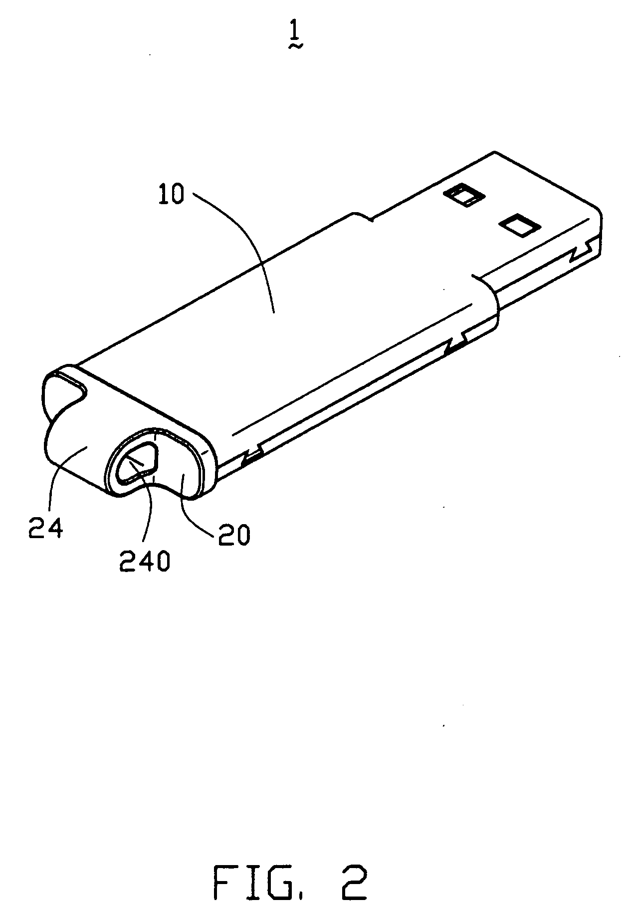
[0020] the insulative housing 20 is received in the mating port 110 and includes a planar body 21 and a rear portion 22. A retaining portion 23 parallel extends from the rear portion 22 and forms a bump 230 at a front portion there...

second embodiment

[0023] Further refer to FIGS. 4-5, the present invention provides a USB 1′ having a metal casing 10′. The metal casing 10′ is formed by a single metal sheet which is integrally stamped into a mating port 110′ and a receiving port 120′. The receiving port 120′ forms a plurality of latches 101′ at side edges thereof. The mating port 110′ includes two parts, wherein each part defines a plurality of latches 101′ at side edges thereof. Therefore, when the single metal sheet is bent into the metal casing 10′, the latches 101′ of the receiving port 120′ are formed at a side wall 121′, and at the same time the latches 101′ of the mating port 110′ are formed at two side walls 111′.

third embodiment

[0024] Further refer to FIG. 6, the present invention discloses a USB 1″ being formed by a single metal sheet. The single metal sheet is stamped integrally into a mating port 110″ and a receiving port 120″. The receiving port 120″ forms a plurality of latches 101″ at side edges and top edges thereof, respectively. The mating port 110″ respectively form a plurality of latches 101″ at bottom edges and side edges thereof. When the single metal sheet is bent into the metal casing 10″, the latches 101″ of the top edges of the receiving port 120″ and the latches 101″ of the bottom edges of the mating port 110″ latch with each other.

[0025] Comparing with the prior art, the metal sheet integrally forms the mating port and the receiving port to effectively reduce the size of the USB. In addition, the predetermined structure prevents the mating port of the USB from disengaging or departing when the USB drops off accidentally.


PUM


Abstract

A universal serial bus connector (1) includes a metal casing (10), an insulative housing (20) and a mating pedestal (30) received in the metal casing, and a printed circuit board (40) with a front portion (41) received in the mating pedestal and a rear portion (42) received in the metal casing. The metal casing forms a mating port (110) and a receiving port (120). The mating port and the receiving port are integrally formed.

Description

BACKGROUND OF THE INVENTION [0001] 1. Field of the Invention [0002] The present invention relates to a portable memory device, and more particularly to a universal serial bus connector. [0003] 2. Description of the Prior Art [0004] The existent portable memory device of an electric appliances is used to process or store data. Such portable memory device is required to have small volume and be easily usable and portable. For example, the currently widely used universal serial bus which has small volume and can be easily carried. [0005] U.S. Pat. No. 6,456,500 B1 issued to Speed Tech on Sep. 24, 2002 discloses a universal serial bus (USB) connector. The conventional USB connector is composed of a bottom cover 1, an upper cover 2, a circuit board 3 and a lateral decorative strip 4. An adapter 31 for engaging with a complementary connector is disposed at a front portion of the circuit board 3. The bottom cover 1 and the upper cover 2 latch with each to form a receiving space for receivi...

Claims


Application Information

Patent Timeline
IPC IPC(8): H01R13/648
CPCH01R13/6581
Inventor ZHAO, QI-JUNLEI, MAO-LIN
Owner HON HAI PRECISION IND CO LTD
Why Eureka
Try Eureka