Optical disc apparatus

a technology of optical discs and clamping devices, which is applied in the field of optical disc apparatuses, can solve the problems of increasing the difficulty of inserting the clamping device reducing the height of the cover, and reducing so as to reduce the height of the top end surface of the clamping device that is inserted into the center hole of the disc, and reduce the overall thickness of the apparatus

Inactive Publication Date: 2006-07-27
HITACHI-LG DATA STORAGE
View PDF8 Cites 2 Cited by
  • Summary
  • Abstract
  • Description
  • Claims
  • Application Information

AI Technical Summary

Benefits of technology

[0003] In both of the above-described apparatuses, while a disc is being chucked, the top end surface of the clamper, which represents the portion to be inserted into the center hole of the disc, does not protrude above the height of an outside flat surface of the cover (top cover), but is positioned below the height of the cover. Thus, it is difficult to reduce the height of the cover, and, therefore, it is difficult to decrease the overall thickness of the apparatus if the height of the top end of the clamper inserted into the center hole of the disc is not reduced. However, when the height of the top end surface of the clamper that is inserted into the center hole of the disc is decreased, the difficulty in inserting the clamper into the center hole of the disc may increase, or other problems which prevent secure chucking of the disc may occur.

Problems solved by technology

Thus, it is difficult to reduce the height of the cover, and, therefore, it is difficult to decrease the overall thickness of the apparatus if the height of the top end of the clamper inserted into the center hole of the disc is not reduced.
However, when the height of the top end surface of the clamper that is inserted into the center hole of the disc is decreased, the difficulty in inserting the clamper into the center hole of the disc may increase, or other problems which prevent secure chucking of the disc may occur.

Method used


Image

  • Optical disc apparatus
  • Optical disc apparatus
  • Optical disc apparatus

Examples


Embodiment Construction

[0012] A preferred embodiment according to the present invention will be described with reference to the drawings.

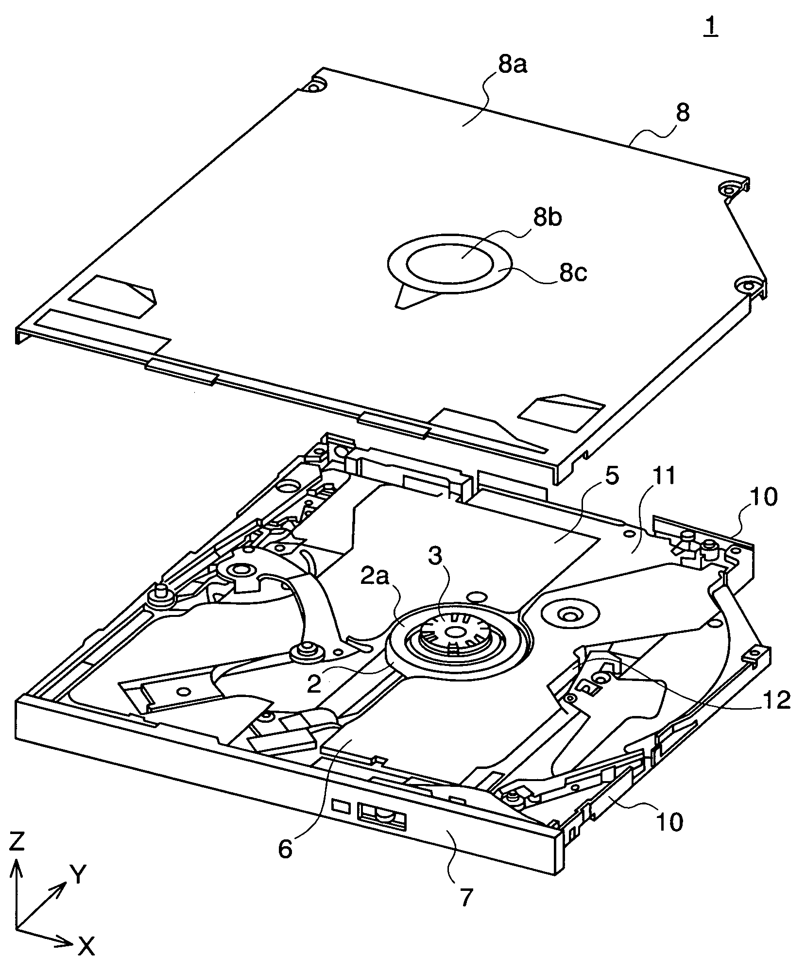
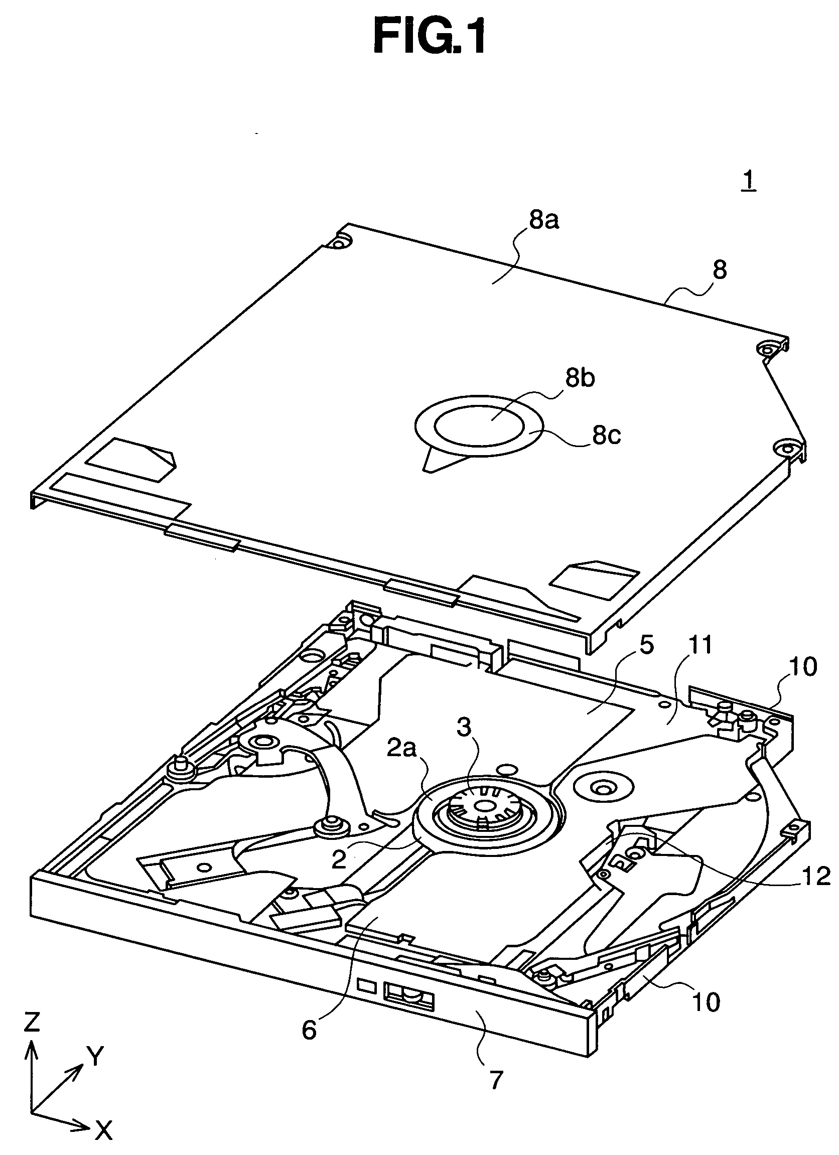
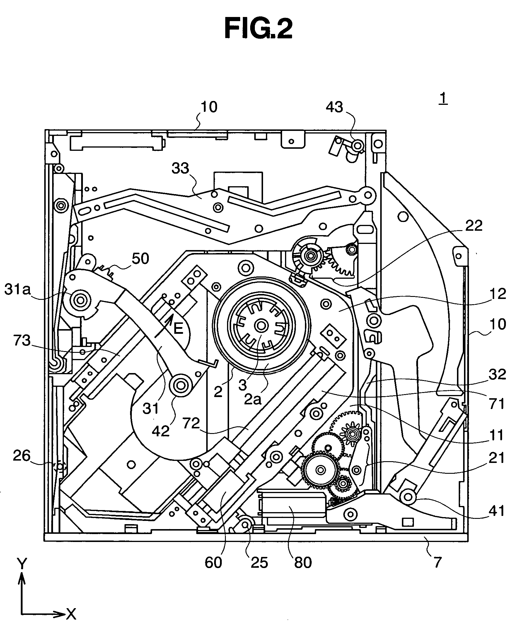
[0013]FIGS. 1 through 3 illustrate an embodiment according to the present invention, wherein: FIG. 1 is a perspective view showing the structure of a slot-in type optical disc apparatus with the top cover removed therefrom, representing an embodiment according to the present invention; FIG. 2 is a plan view showing the inside structure of the optical disc apparatus shown in FIG. 1; and FIG. 3 illustrates the chucking of an optical disc in the optical disc apparatus shown in FIG. 1.

[0014] As shown in FIG. 1, the optical disc apparatus 1 has a disc motor 2 for rotating an optical disc (not shown); a central protrusion clamper 3 mounted on the rotating shaft of the disc motor 2, comprising a central cylindrical protrusion which is inserted into a center hole of the optical disc to keep the optical disc from moving in a radial direction while the optical disc is being chuc...


PUM

PropertyMeasurementUnit
distanceaaaaaaaaaa
thicknessaaaaaaaaaa
surface areaaaaaaaaaaa

Abstract

In order to decrease the total thickness of an optical disc apparatus the optical disc apparatus is provided with a structure in which an optical disc contacts the surface of a top cover facing the optical disc so that the top end surface of a cylindrical protruding clamper inserted into the center hole of the optical disc protrudes from a through hole of the top cover and is positioned higher than the flat upper surface of the top cover in the disc flat surface area over the disc, while the optical disc is being chucked.

Description

BACKGROUND OF THE INVENTION [0001] The present invention relates in general to an optical disc apparatus for recording or reproducing information on or from an optical disc, and, more particularly, the invention relates to a technique which is useful for reducing the thickness of an optical disc apparatus. [0002] Known technologies in the field of the present invention are disclosed JP-A-2002-352497 and JP-A-2004-39198, for example. A small-sized thin disc apparatus is disclosed in JP-A-2002-352497, in which a turn table is shifted by a shifting mechanism relative to a contact member provided in an upper casing. Then, a disc holding mechanism is inserted into the center hole of the disc by pressing the disc surface against the contact member surface, so that the disc is laid (chucked) on the turn table. A disc drive apparatus is disclosed in JP-A-2004-39198, which also includes a chucking mechanism in which a disc spindle mounted on a turn table can be set into and released from a d...

Claims


Application Information

Patent Timeline
Patent Type & Authority Applications(United States)
IPC IPC(8): G11B17/04
CPCG11B17/0288G11B17/051G11B7/00G11B17/02G11B17/028
Inventor ONUMA, HIDEYUKIHAMAIE, SEIJIKIRIHARA, SOJIRO
Owner HITACHI-LG DATA STORAGE
Why Eureka
Try Eureka