Height adjustment structure for a canopy

a technology of height adjustment and canopy, applied in the field of canopy, can solve the problems of inability to adjust and height of existing canopy, and achieve the effects of simple structure, convenient use, and change of roof heigh

Inactive Publication Date: 2006-08-03
HWANG JOHN PHECHIT
View PDF6 Cites 24 Cited by
  • Summary
  • Abstract
  • Description
  • Claims
  • Application Information

AI Technical Summary

Benefits of technology

[0006] The present invention solves the above technical problem by providing a simple height adjustment structure of the canopy that is convenient to use.
[0009] Because holes are provided along the pole, when the sliding sleeve slides up and down to a certain location along the pole, the locking pin pressing against the surface of the pole will fall into the hole to lock the sliding sleeve. The sliding sleeve may be connected with the roof frame of the canopy and the height of the roof may be changed by adjusting the location of the sliding sleeve on the pole. The height adjustment structure has a simple structure that used the cooperation between the locking pin and the holes on the pole to lock the sliding sleeve to the pole. In addition, the use of a press plate structure and lever action makes it easy to use.

Problems solved by technology

For example, due to change of the direction of the sun, proper adjustment may be required in the height of the canopy, but the height of existing canopies depend on the height of the vertical poles in the framework and cannot be adjusted.

Method used


Image

  • Height adjustment structure for a canopy
  • Height adjustment structure for a canopy
  • Height adjustment structure for a canopy

Examples


Embodiment Construction

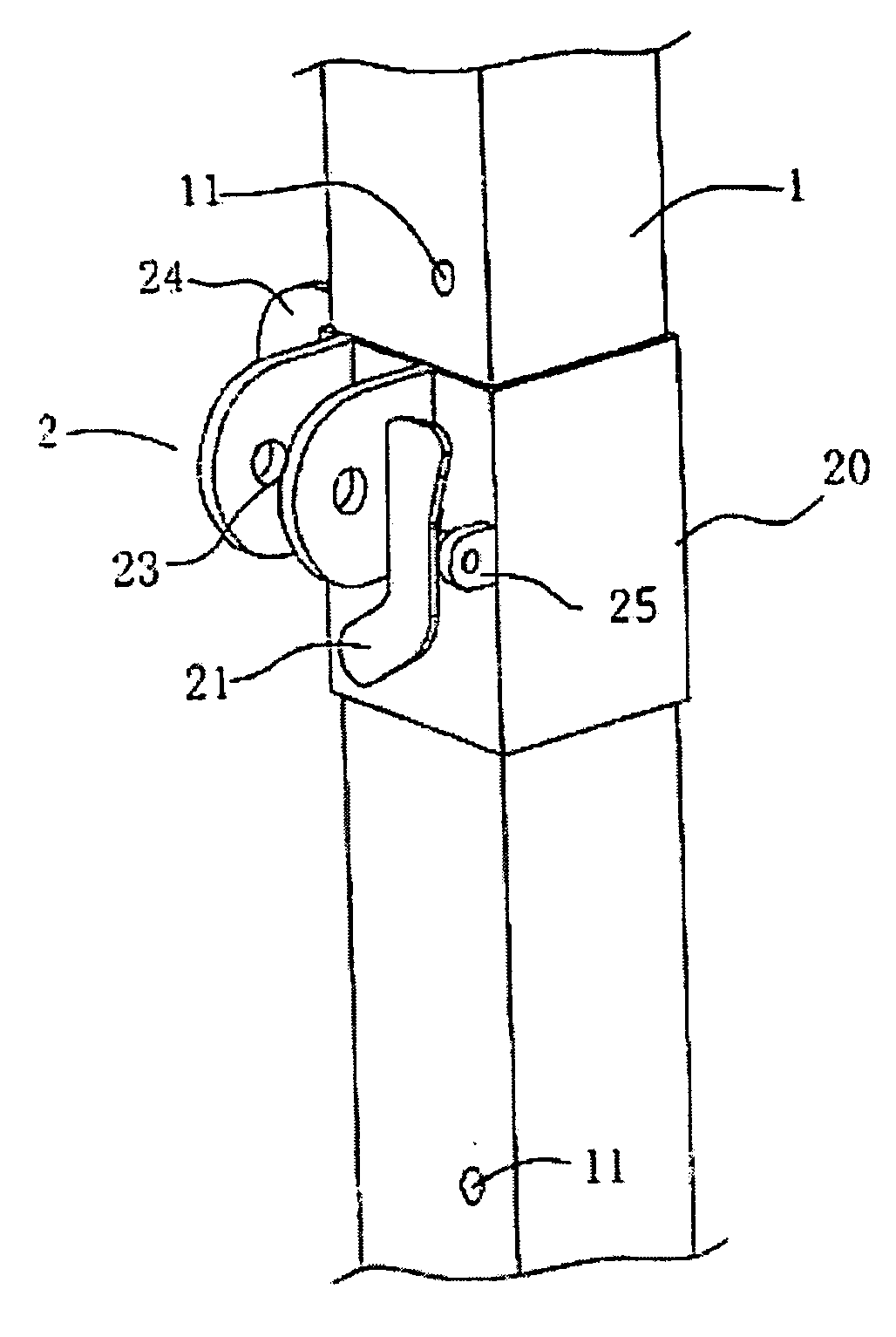
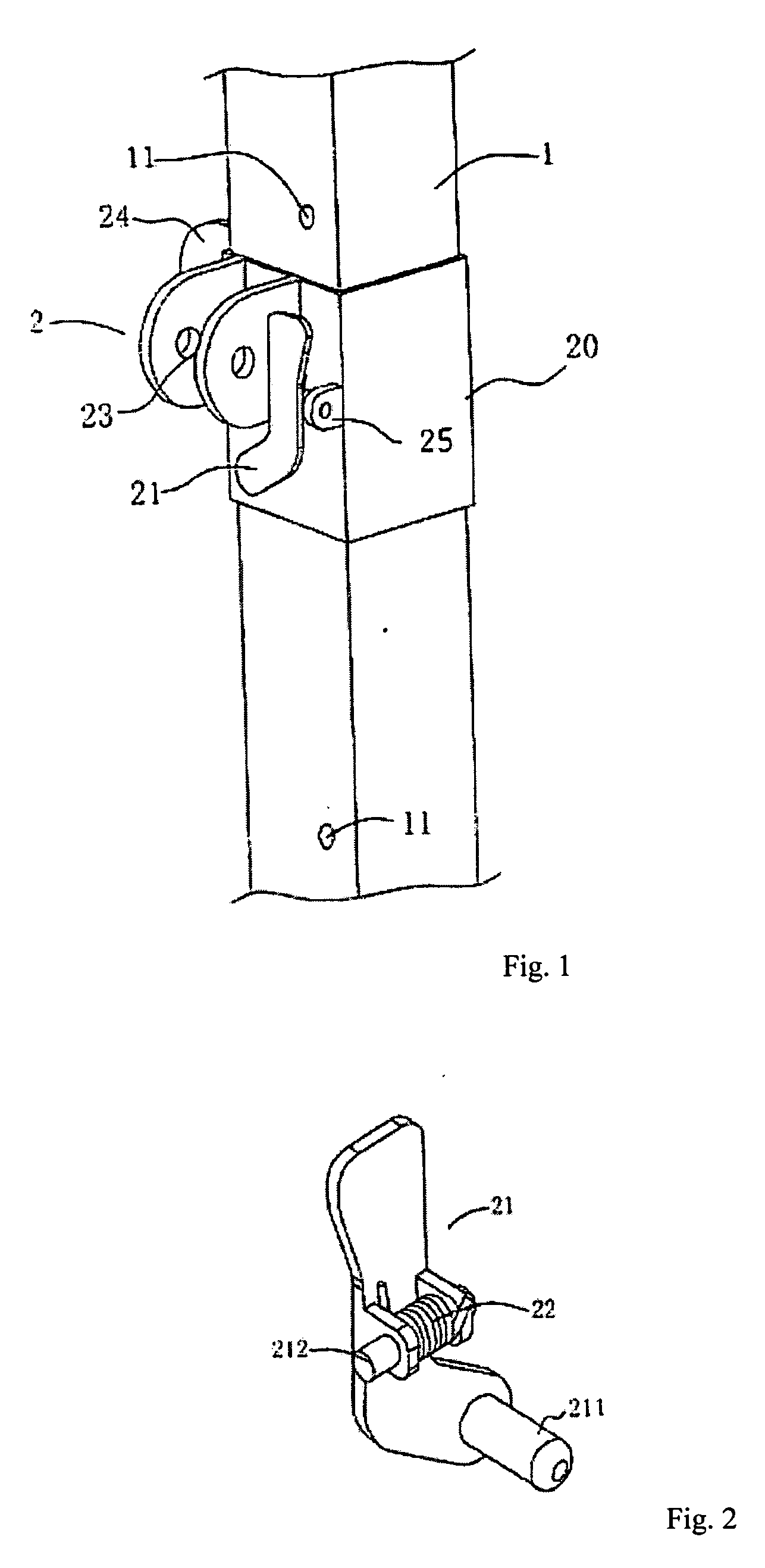
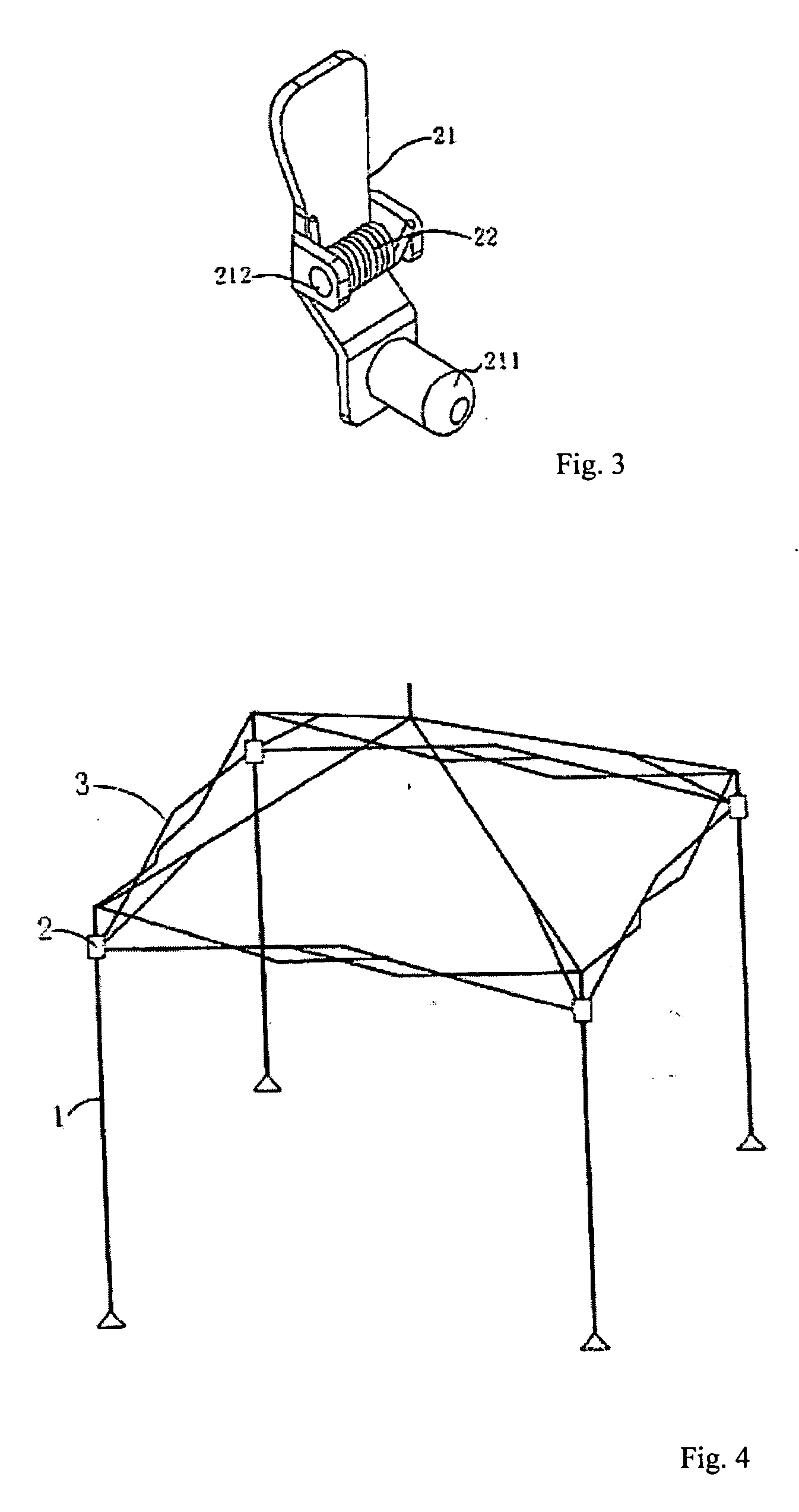
[0015] As shown in FIGS. 1 and 2, a height adjustment structure for a canopy according an embodiment of the present invention includes a vertical pole 1 and a sliding sleeve 2 disposed around the pole. A spring loaded press plate 21 is pivotally mounted on a sidewall 20 of the sliding sleeve 2 between two protruding plates 25 by a mounting pin 212 which extends through a pair of holes on the plates 25. A spring 22 is wound round the mounting pin 212 to bias the press plate 21. One end of the press plate 21 has a locking pin 211 which extend into a through hole (not shown in the drawings) in the sidewall of the sleeve 20. Under the spring tension of the spring 22, the press plate 21 urges the locking pin 211 against the surface of the pole 1 inside the sleeve 20.

[0016] Connecting parts are formed on the sleeve 20 to connect it with other components of the canopy. In the illustrated example, the connecting parts are a pair of plates 23, 24 with through holes.

[0017] In addition, seve...


PUM


Abstract

A canopy has a framework including a plurality of vertical poles and a roof frame. A height adjustment structure for adjusting the height of the roof frame includes a sliding sleeve disposed around each vertical pole, to which the roof frame is connected. The sleeve can slide along the pole so that a through hole on a sidewall of the sleeve is aligned with one of the holes provided on the vertical pole. A spring loaded press plate pivotally mounted on the sidewall of the sleeve has a locking pin at one end which can extend into the through hole on the sleeve and the hole on the pole to lock the sleeve at a desired height along the pole.

Description

BACKGROUND OF THE INVENTION [0001] 1. Field of the Invention [0002] This invention relates to a canopy, and in particular, it relates to a height adjustment structure for a canopy. [0003] 2. Description of the Related Art [0004] Canopies are useful for outdoor activities as a sun or rain shelter. For example, it may provide a place for resting and dining at outdoor parties, or provide a place for resting when camping, etc. Existing canopies are typically made up of framework and a cover. To make it convenient for carrying and storing, the framework can be disassembled and re-assembled when needed. The framework may be disassembled when the canopy is not in use for convenient carrying and storing. Even so, there are still some shortcomings in existing canopies. Under different circumstances or at different times, users may have different requirements for the height of the canopy. For example, due to change of the direction of the sun, proper adjustment may be required in the height o...

Claims


Application Information

Patent Timeline
Patent Type & Authority Applications(United States)
IPC IPC(8): E04H15/44
CPCE04H15/50
Inventor HWANG, JOHN PHECHIT
Owner HWANG JOHN PHECHIT
Why Eureka
Try Eureka