Wet type multi-plate clutch

Inactive Publication Date: 2006-08-03
COTTRELL +1
View PDF8 Cites 8 Cited by
  • Summary
  • Abstract
  • Description
  • Claims
  • Application Information

AI Technical Summary

Benefits of technology

[0015] By engaging the projection provided on the clutch housing with the recessed portion of the piston, the relative rotation between the piston and the clutch housing can be prevented. As a result, the rotation of the pis

Problems solved by technology

If the piston is rotated upon engaging the friction engaging elements, due to the rotation of the piston, the O-ring arranged around the piston may be damaged.
Further, due to the rotation of the piston, a spring connected to the piston may be twisted to damage the spring.
As a result, peripheral members may be damaged, thereby causing mal-function of the clutch.
S50-101747, if the pawl portion is provided on the drive plate, the pawl portion abuts against the groove of the piston repeatedly for preventing

Method used


Image

  • Wet type multi-plate clutch
  • Wet type multi-plate clutch
  • Wet type multi-plate clutch

Examples


Example

[0020] Now, embodiments of the present invention will be fully explained with reference to the accompanying drawings. Incidentally, in the drawings, the same parts or elements are designated by the same reference numerals.

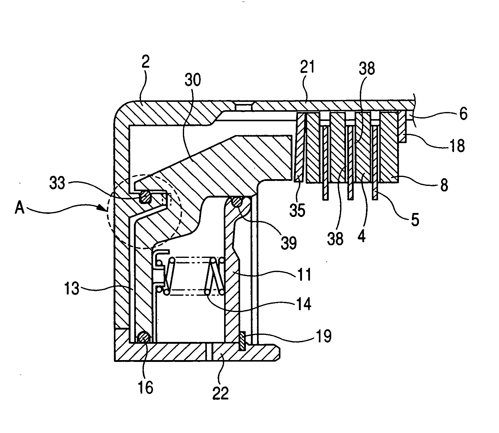
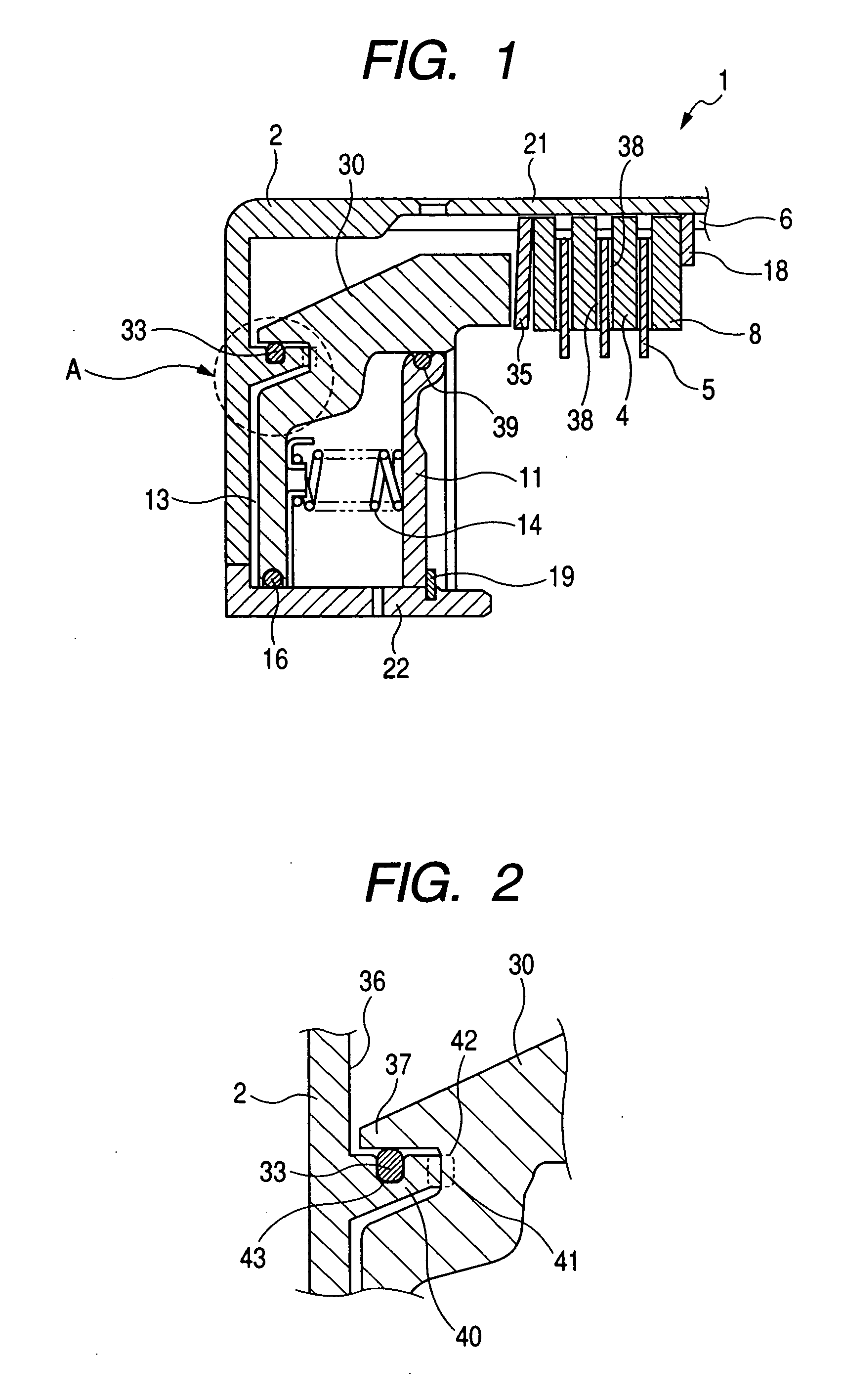
[0021]FIG. 1 is an axial sectional view showing a wet type multi-plate clutch 1 according to an embodiment of the present invention, and FIG. 2 is an enlarged view of a portion shown by a circle A in FIG. 1.

[0022] In the wet type multi-plate clutch 1, a clutch housing 2 and a hub (not shown) are arranged on a common axis. A spline 6 is formed in an inner peripheral surface of an outer cylindrical portion of the clutch housing 2 and separator plates 4 as first friction engaging elements are received in the spline, and friction plates as second friction engaging elements are received in a spline formed in an outer periphery of the hub (not shown) in such a manner that the separator plates and the friction plates are alternately arranged on a common axis. Friction m...


PUM


Abstract

The present invention provides a wet type multi-plate clutch comprising a first friction engaging element coaxially arranged within a clutch housing, a second friction engaging element alternately disposed with the first friction engaging element and a piston for applying an axial load to engage the first and second friction engaging elements with each other and wherein a projection protruding toward the piston is provided on the clutch housing and a recessed portion is provided in the piston so that a relative rotation between the clutch housing and the piston is prevented by engaging the projection with the recessed portion.

Description

BACKGROUND OF THE INVENTION [0001] 1. Field of the Invention [0002] The present invention relates to a wet type multi-plate friction engaging apparatus used in an automatic transmission of a vehicle and the like. More particularly, the present invention relates to a wet type multi-plate friction engaging apparatus including means for preventing a relative rotation between a clutch housing and a piston. [0003] 2. Related Background Art [0004] In a wet type multi-plate friction engaging apparatus, a power is transmitted by engaging a plurality of friction engaging elements disposed within a clutch housing with each other. In order to apply an axial urging force to the friction engaging elements, a piston shiftable in an axial direction is provided within the clutch housing. [0005] The piston is shifted in the axial direction by supplying oil pressure into an oil pressure chamber defined between the piston and the clutch housing, thereby tightening or engaging the friction engaging ele...

Claims


Application Information

Patent Timeline
IPC IPC(8): F16D25/0638
CPCF16D25/0638
Inventor ICHIKAWA, KIYOKAZU
Owner COTTRELL
Why Eureka
Try Eureka