
Wide-angle lens system

a wide-angle lens and wide-angle technology, applied in the field of compact wide-angle lens systems, can solve the problems of long total lens length and super-wide-angle regions of photographs, and achieve the effect of excellent optical performan

Active Publication Date: 2006-08-03
KONICA MINOLTA OPTO
View PDF4 Cites 16 Cited by
  • Summary
  • Abstract
  • Description
  • Claims
  • Application Information

AI Technical Summary

Benefits of technology

[0007] In view of the problem described above, the present invention has been made, and it is an object of the invention to provide a low-cost, compact super-wide-angle lens system which has an excellent optical performance.
[0018] According to the present invention, a low-cost, compact wide-angle lens system having a favorable optical performance can be provided.

Problems solved by technology

However, these wide-angle lens systems have a total angle of view of 120 degrees which is insufficient to photograph super-wide-angle regions.
However, this super-wide-angle lens system is composed of as very many as eight lens elements in total with a complicated structure and a very long total lens length.

Method used


Image

  • Wide-angle lens system
  • Wide-angle lens system
  • Wide-angle lens system

Examples


example 1

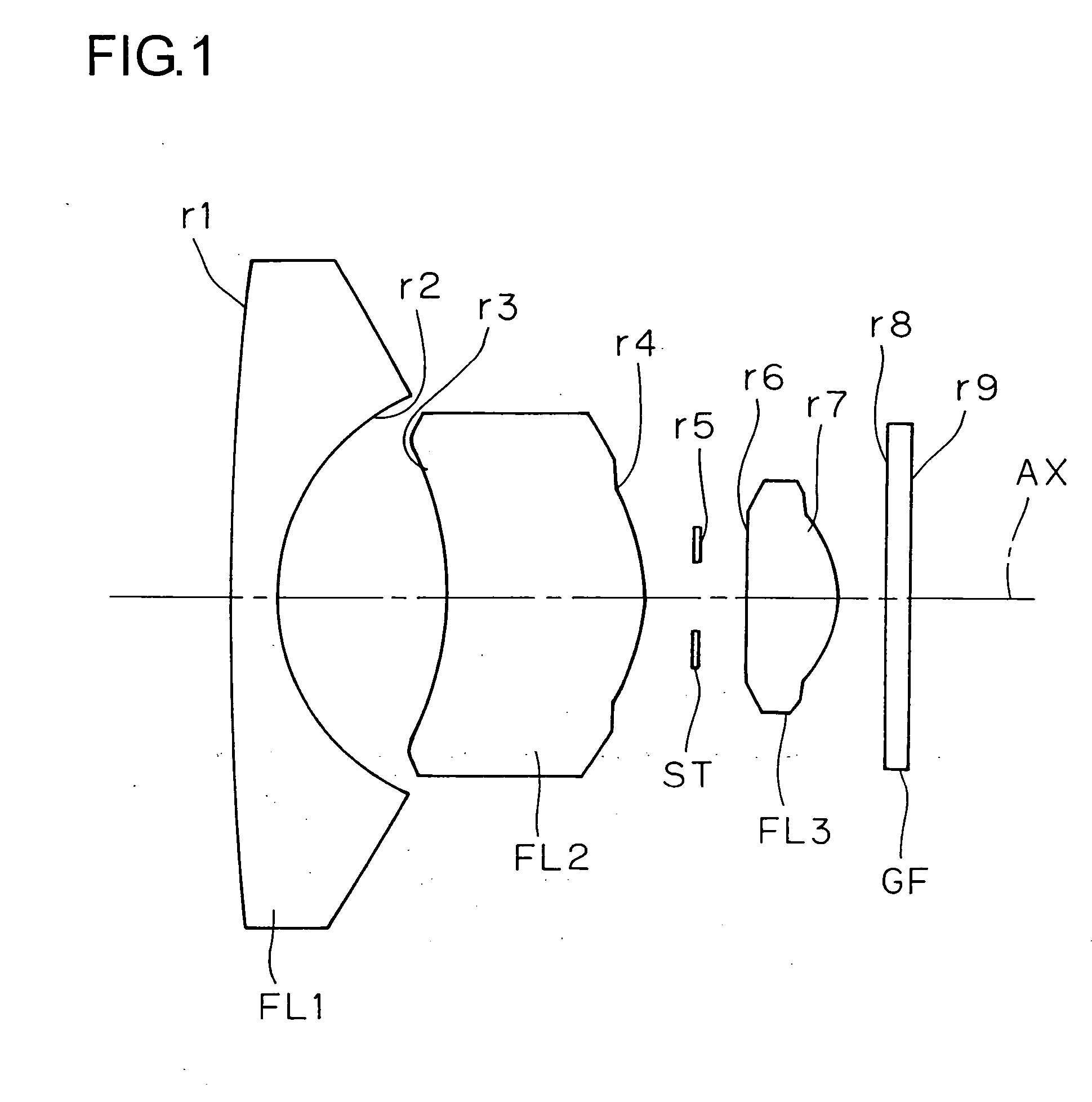
[0051] f=2.097

[0052] FNO=2.8

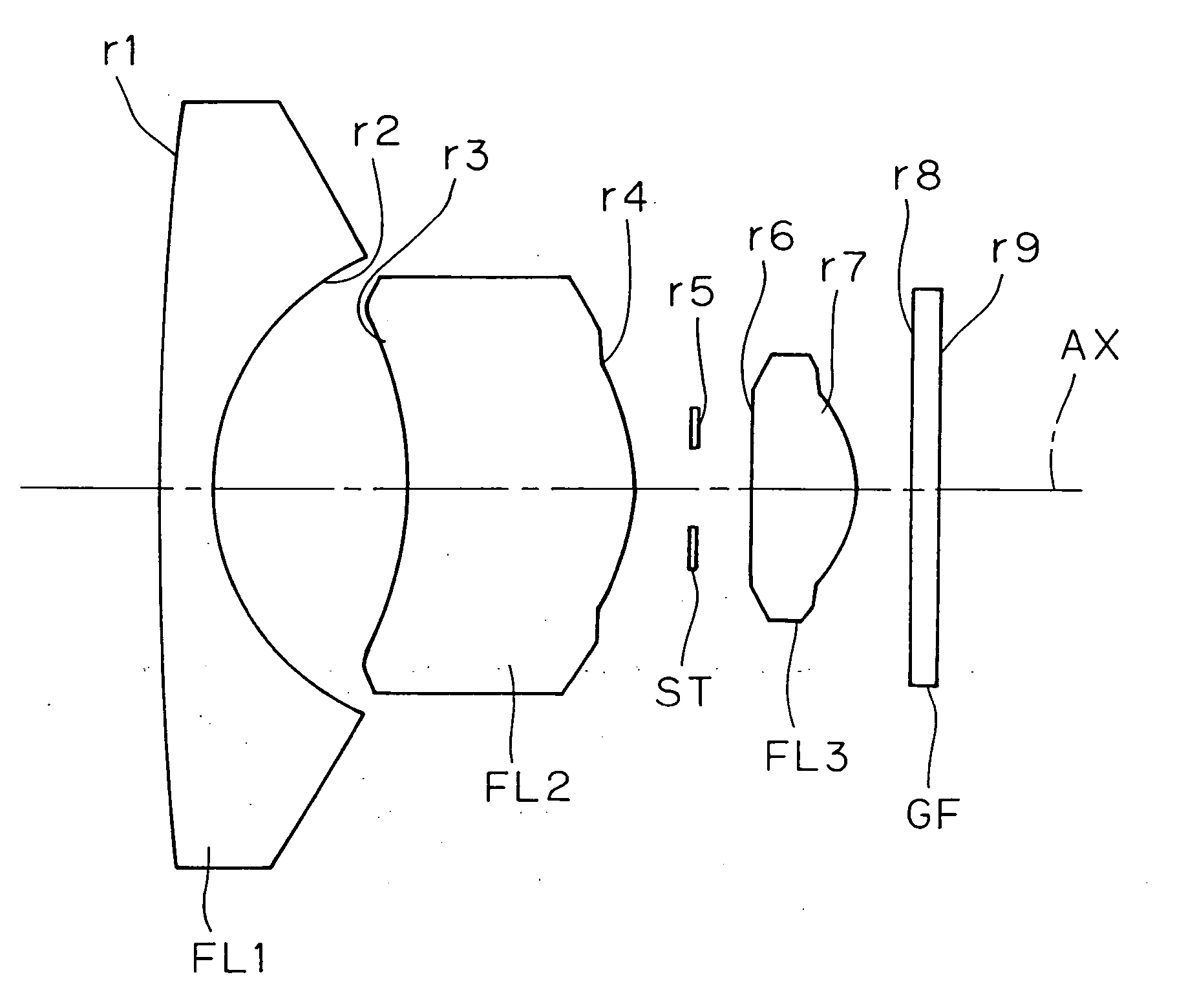
[Radius of[Axial[Refractive[Abbecurvature]distance]index]number]r1 = 66.638d1 = 1.053N1 = 1.58913ν1 = 61.25(FL1)r2 = 4.898d2 = 3.592N2 = 1.52510ν2 = 56.38(FL2)r3* = −6.435d3 = 4.212N3 = 1.52510ν3 = 56.38(FL3)r4* = −3.405d4 = 1.169N4 = 1.51680ν4 = 64.20(GF)r5 = ∞(ST)d5 = 1.091r6* = −21.168d6 = 1.976r7* = −2.124d7 = 1.000r8 = ∞d8 = 0.500r9 = ∞Σd = 14.593

[0053] [Aspherical surface data of the third surface (r3)][0054]ε=1.0 [0055] A4=0.15045×10⁻² [0056] A6=0.16607×10⁻³ [0057] A8=−0.40815×10⁻⁴ [0058] A10=0.21958×10⁻⁵

[0059] [Aspherical surface data of the fourth surface (r4)][0060]ε=1.0 [0061] A4=0.13444×10⁻¹ [0062] A6=−0.16674×10⁻² [0063] A8=0.18304×10⁻³ [0064] A 10=−0.45788×10⁻⁶

[0065] [Aspherical surface data of the sixth surface (r6)][0066]ε=1.0 [0067] A4=−0.10863×10⁻¹ [0068] A6=−0.16249×10⁻² [0069] A8=0.88957×10⁻² [0070] A10=−0.20908×10⁻²

[0071] [Aspherical surface data of the seventh surface (r7)][0072]ε=1.0 [0073] A4=0.12301×10⁻¹ [0074] A6=0.24208×10...

example 2

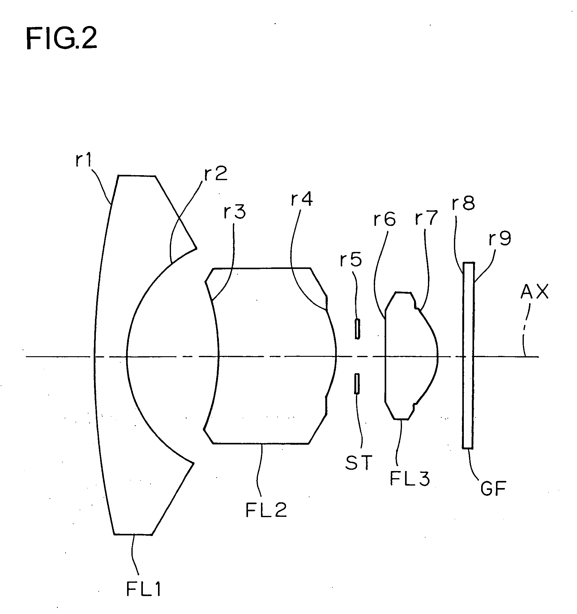
[0077] f=1.875

[0078] FNO=2.8

[Radius of[Axial[Refractive[Abbecurvature]distance]index]number]r1 = 30.486d1 = 1.327N1 = 1.72916ν1 = 54.67(FL1)r2 = 4.779d2 = 3.677N2 = 1.52510ν2 = 56.38(FL2)r3* = −6.646d3 = 4.633N3 = 1.52510ν3 = 56.38(FL3)r4* = −3.158d4 = 0.810N4 = 1.51680ν4 = 64.20(GF)r5 = ∞ (ST)d5 = 1.195r6* = −11.029d6 = 1.978r7* = −1.971d7 = 1.000r8 = ∞d8 = 0.400r9 = ∞Σd = 15.019

[0079] [Aspherical surface data of the third surface (r3)][0080]ε=1.0 [0081] A4=0.54002×10⁻² [0082] A6=−0.85537×10⁻³ [0083] A8=0.72417×10⁻⁴ [0084] A10=−0.27045×10⁻⁵

[0085] [Aspherical surface data of the fourth surface (r4)][0086]ε=1.0 [0087] A4=0.20553×10−[0088] A6=−0.57032×10⁻² [0089] A8=0.13338×10⁻² [0090] A10=−0.71240×10⁻⁴

[0091] [Aspherical surface data of the sixth surface (r6)][0092]ε=1.0 [0093] A4=−0.39253×10⁻² [0094] A6=−0.57908×10⁻² [0095] A8=0.13485×10⁻¹ [0096] A10=−0.36536×10⁻²

[0097] [Aspherical surface data of the seventh surface (r7)][0098]ε=1.0 [0099] A4=0.15550×10⁻¹ [0100] A6=0.64826×101...


PUM


Abstract

A wide-angle lens system includes: from the object side, (1) a first lens element formed of glass having both surfaces thereof so formed as to be spherical, having a meniscus shape convex to the object side, and having a negative optical power; (2) a second lens element formed of plastic having a meniscus shape convex to the image side and having a positive optical power; (3) an aperture stop; and (4) a third lens element formed of plastic having a meniscus shape convex to the image side and having a positive optical power, and the wide-angle lens system includes three lens elements in total. This permits providing a low-cost, compact super-wide-angle lens system having a favorable optical performance.

Description

[0001] This application is based on Japanese Patent Application No. 2005-024517 filed on Jan. 31, 2005, the contents of which are hereby incorporated by reference. BACKGROUND OF THE INVENTION [0002] 1. Field of the Invention [0003] The present invention relates to a compact wide-angle lens system, and more specifically to a low-cost, compact super-wide-angle lens system for a solid-state image sensor, which super-wide-angle lens system is suitable for a digital image pickup apparatus such as a TV telephone, a video intercom, a monitoring camera, an on-vehicle camera, or the like, which has a favorable optical performance, and which has a total angle of view of approximately 170 degrees. [0004] 2. Description of the Prior Art [0005] Wide-angle lens systems for solid-state image sensors have been conventionally widely known. For example, Japanese Patent Application Laid-open No. H6-34879 and Japanese Patent Application Laid-open No. 2001-337268 disclose wide-angle lens system with thr...

Claims


Application Information

Patent Timeline
IPC IPC(8): G02B13/04
CPCG02B9/12G02B13/0035G02B13/06G02B13/04G02B13/18G02B1/041G03B9/02
Inventor HIROSE, MASATOSHIISONO, MASASHI
Owner KONICA MINOLTA OPTO
Learn More