Method and apparatus for remote management of a monitoring system over the internet

a monitoring system and internet technology, applied in the field of monitoring systems, can solve the problems of limiting the access to the network from the internet, remote users are unable to penetrate the protection, and modifications may be difficult, so as to achieve dynamically balance the network load of the system and reduce the load

Inactive Publication Date: 2006-08-03
AXIS
View PDF31 Cites 49 Cited by
  • Summary
  • Abstract
  • Description
  • Claims
  • Application Information

AI Technical Summary

Benefits of technology

[0022] By providing a method like this it becomes possible to balance the network load of the system dynamically in spite of the fact that the monitoring device is arranged on a private network behind an access limiting device, i.e. if the load on the control server or on the public network path to the control server becomes to high.
[0023] According to a further embodiment the control server to move the open path to are selected by the monitoring device from a list of control servers stored in the monitoring device. The se...

Problems solved by technology

However, most private networks, home networks, corporate networks, etc. are connected to the Internet via some device that limits the access to the network from the Internet.
Thus, one problem of such a monitoring system is that many functions, e.g. control of the monitoring device or devices, require transactions initiated by either the control center or the remote user and that the monitoring device or devices are arranged in a private network behind an access limiting device.
Accordingly, the control center or the remote user either are unable to penetrate the protection installed or do not have knowledge of the address of the...

Method used


Image

  • Method and apparatus for remote management of a monitoring system over the internet
  • Method and apparatus for remote management of a monitoring system over the internet
  • Method and apparatus for remote management of a monitoring system over the internet

Examples


Embodiment Construction

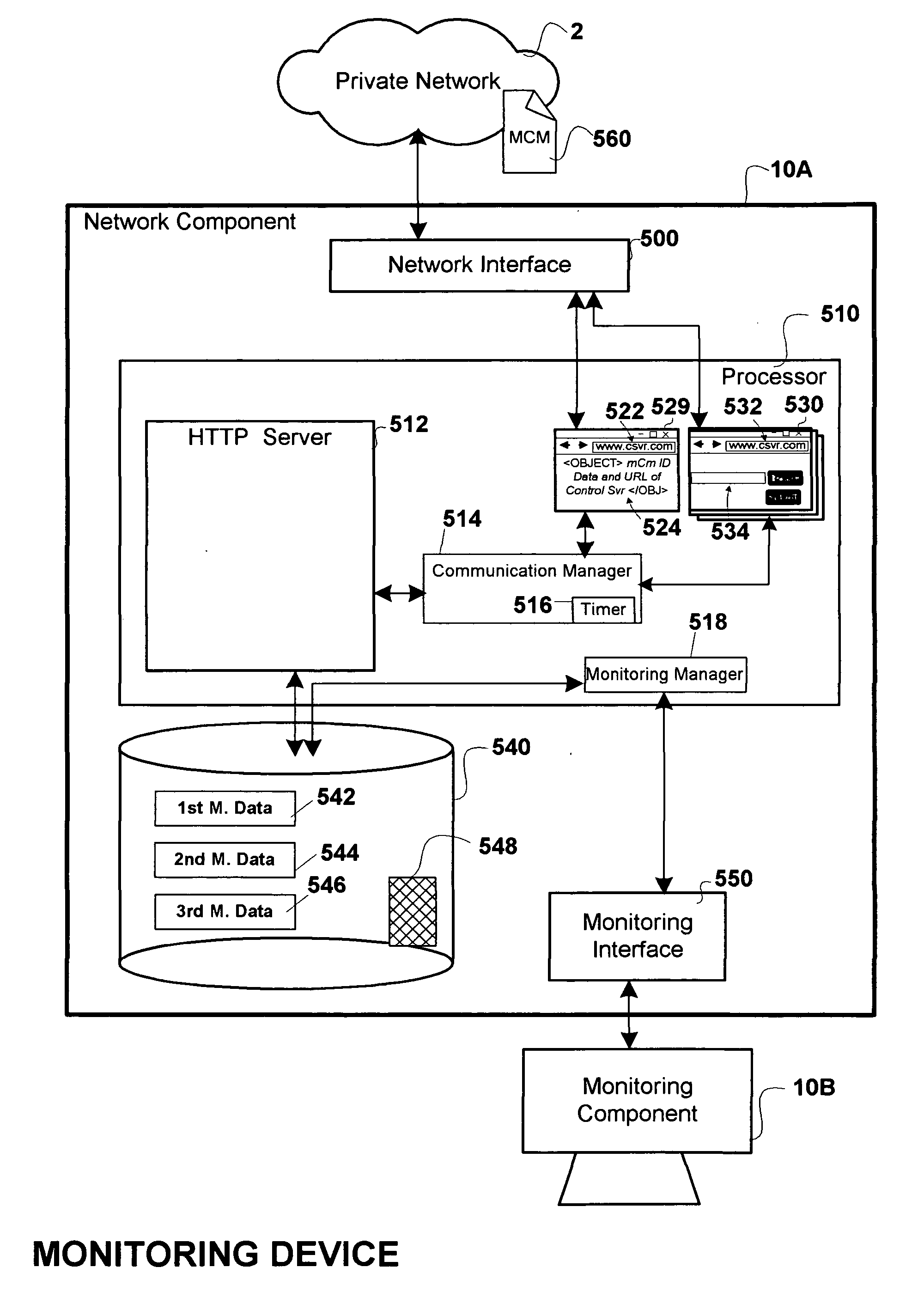
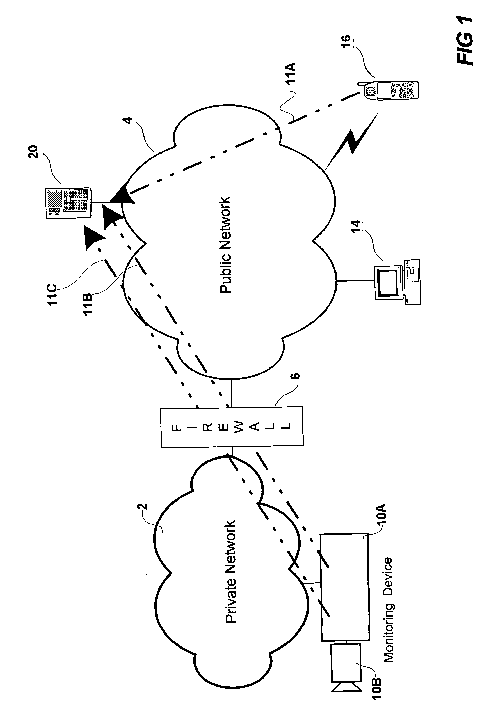
[0042]FIG. 1 is a network diagram of one embodiment of a monitoring system according to the present invention. The monitoring system includes a private network 2, e.g. a Local Area Network (LAN) arranged in a home, at an office, in a factory, in a park or a garden, at a car park, or in any area or premises that is interesting to monitor. The public and private networks are packet switched networks supporting the HTTP communication protocol. The private network 2 is connected to a public network 4, e.g. the Internet, via an access limiting device 6, e.g. a firewall, a NAT (Network Address Translation), a proxy server, an ISP (Internet Service Provider) providing dynamic addresses. The access limiting device 6 is limiting the access to the private network 2 from the public network 4 in different ways depending on the specific type of limiting device. For example, a firewall is generally arranged to prohibit access to devices in the private network from a public network.

[0043] Further...


PUM


Abstract

A Monitoring system and a method in a monitoring system comprising a public network, a private network, an access limiting device arranged to limit the access of the private network from the public network, and a control server connected to the public network. The monitoring system further comprises a monitoring device connected to the private network and being arranged to send an HTTP request to the control server. The control server being arranged to send a HTTP response to the monitoring device in response to the HTTP request, wherein the HTTP header's ‘Content-Length’ field of the HTTP response is not defined or wherein the HTTP header's ‘Content-Length’ field is set to a number that is large enough to enable transport of a plurality of future control messages as part of an over time stretched HTTP response resulting in an open path from the control server to the monitoring device through the access limiting device and wherein the control server is arranged to send control messages to the monitoring device via said open path.

Description

CROSS REFERENCE TO RELATED APPLICATION [0001] This application claims the benefit of prior filed co-pending Provisional Application No. 60 / 647,116 filed on Jan. 25, 2005 entitled “Monitoring System and Method for Accessing a Monitoring Device of a Monitoring System” (Atty. Docket # AWAPP012P) and of prior filed Swedish Patent Application No. 0500071-6 filed Jan. 10, 2005 entitled “Monitoring System and Method for Accessing a Monitoring Device of a Monitoring System” both of which are incorporated herein by reference in their entirety as if fully set forth herein.BACKGROUND OF THE INVENTION [0002] 1. Field of Invention [0003] The present invention relates to a monitoring system including a public network, a private network, and an access limiting device arranged to limit the access of the private network from the public network. Further the present invention relates to a method for accessing a monitoring device of such a monitoring system from the public network. [0004] 2. Descriptio...

Claims


Application Information

Patent Timeline
IPC IPC(8): G06F15/173
CPCH04L29/12509H04L61/2567H04L63/029H04L67/025
Inventor TULLBERG, JOACIMADOLFSSON, JOHAN
Owner AXIS
Why Eureka
Try Eureka