High security lock mechanism

a high-security, lock mechanism technology, applied in the field of high-security lock mechanism, can solve the problems of inability to use long-life batteries, require substantial amounts of electric power, and even to power a small microprocessor, and achieve the effect of restoring security

Inactive Publication Date: 2006-08-10
LOCK II
View PDF54 Cites 15 Cited by
  • Summary
  • Abstract
  • Description
  • Claims
  • Application Information

AI Technical Summary

Benefits of technology

[0012] It is another object of this invention to provide a locking mechanism actuated by the input of a selected combination code followed by the delivery of a very small amount of electrical power generated during input of a user-selected combination code to a low friction engagement means to put the same in a position to enable purely manual unlocking of the mechanism thereafter.
[0014] It is an even further object of this invention to provide a secure locking mechanism which is unlocked by the provision of a preselected combination code within a specified time followed by the provision of a very small amount of electrical power to move an engagement element to a position to enable solely manual unlocking of the mechanism thereafter.
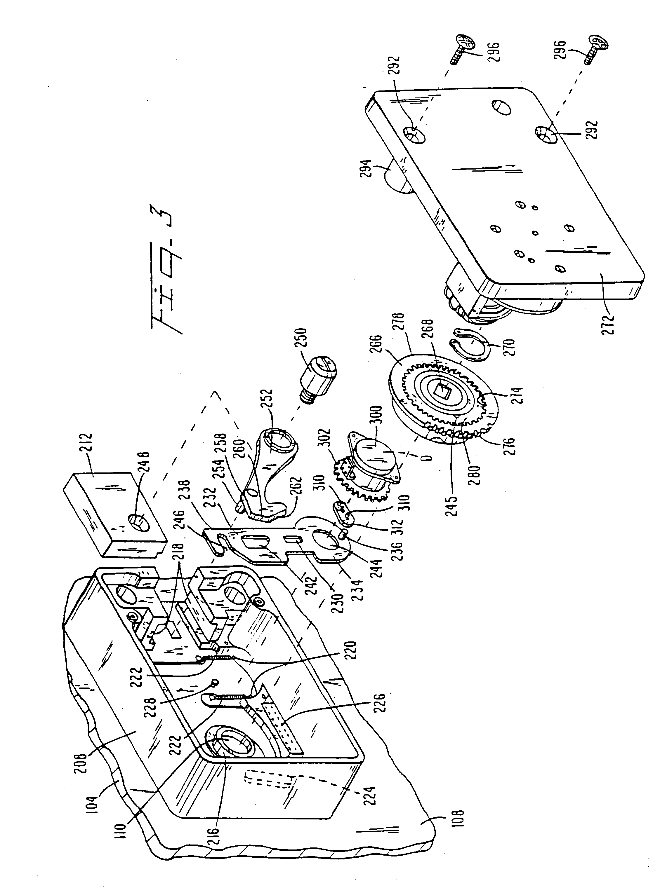
[0016] These and other related objects are realized, according to a preferred embodiment of the invention, by providing a locking mechanism which comprises a first means for moving an engagement element from a disengaged position to an engageable position thereof solely upon receipt of a controlled predetermined electrical power output, a manually operated second means for engaging the engagement element when the latter is in its engageable position for thereby manually moving the first means further in a first direction and back in a second direction, and third means for driving a lock-bolt engaged by the further movement of the first means to drive the lock-bolt to locking and unlocking positions thereof in correspondence with movements of the first means in the first and second directions respectively. Movement of the first means in the second direction restores security by returning the engagement element to its disengaged position when the lock-bolt reaches its locked position.

Problems solved by technology

A major problem with such devices is that they require substantial amounts of electric power to perform their locking and unlocking functions.
In fact, for many applications, the use of long-life batteries, even to power a small microprocessor, may also be deemed unacceptable.

Method used


Image

  • High security lock mechanism
  • High security lock mechanism
  • High security lock mechanism

Examples


first embodiment

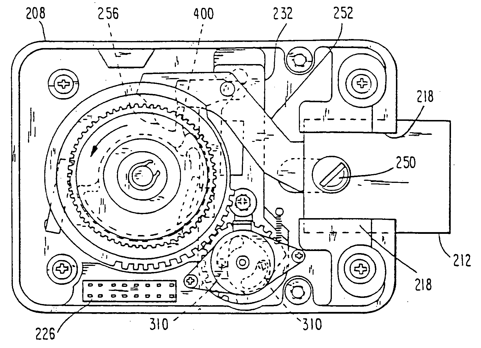
[0059] Referring to FIGS. 7A-7C, a view intended to be generally comparable to the view of the first embodiment, per FIG. 6A, a lock-bolt 212 is slidably guided within guides 218, 218 and a pivot 250 pivotably connects lock-bolt 212 to a lever arm 702 which has a hook 704 at a distal end thereof. The extreme distal end of lever arm 702 ends in a frontal surface 706, the shape of hook 704 being defined by an elongate curved surface 708 which meets a rear hook surface 710 at a point 712 of the hook. These surfaces are polished smooth. Lever arm 702, at a point intermediate its ends, is provided with a spring connection pin 714. A first spring 716, of selected length and stiffness, is hooked at one end to spring connection pin 714 and at another end to a first spring attachment point 718 at an upper portion of lock casing 208. Absent the application of an externally applied force, first spring 716 provides a sufficient biasing force to hold lever arm 702 with its smooth front surface 7...

third embodiment

[0075] Note that, as with the two previously described embodiments, in this third embodiment the basic principle utilized is to employ a very small electrical power pulse to cause a light-weight, low-friction electric motor to cause a small rotatable element to rotate to initiate an engagement between a lever arm and a manually driven rotatable rotary element to enable delivery of a manual force to drive lock bolt 212 from its locking to its unlocking position. Note also that, as with the previous embodiments, such an engagement becomes possible only after the microprocessor has received a correct and complete combination code input from the user, and only when the user manually torques rotary element 806 thereafter.

[0076] In order to put the locking mechanism in its locking state, the user must manually rotate rotary element 806 in the contrary direction, i.e., clockwise in FIG. 8C. Co-action between the smooth, curved, outer edge of hook 804 and hook-engaging detent 808 will then ...


PUM


Abstract

A self-powered electric lock includes a lock bolt and a first engagement element having disengaged and engageable positions. An electric actuator includes an output operative to move the first engagement element to its engageable position. A manually operated rotatable member is operatively coupled to the first engagement element when the first engagement element is in its engageable position. A lock bolt drive mechanism is coupled to the lock bolt and to the first engagement element when the first engagement element is in its engageable position. The movable output moves the first engagement element to its engageable position upon input of correct electronic data. An electricity generator is coupled to the manually operated rotatable member. The electricity powers the electric actuator and an electronic data input device. The manually operated rotatable member is also used to actuate the lock bolt drive mechanism and retract the lock bolt.

Description

[0001] This application is a continuation of application Ser. No. 10 / 965,305 filed on Oct. 14, 2004 (pending) which is a continuation of application Ser. No. 10 / 391,830 filed on Mar. 19, 2003 (now U.S. Pat. No. 6,813,917) which is a continuation of application Ser. No. 09 / 985,975 filed Nov. 7, 2001 (now U.S. Pat. No. 6,546,769) which is a continuation of application Ser. No. 09 / 409,760 filed Sep. 30, 1999 (now U.S. Pat. No. 6,314,773) which is a continuation of application Ser. No. 08 / 985,901 filed Dec. 5, 1997 (now U.S. Pat. No. 5,960,655) which is a continuation of application Ser. No. 08 / 593,725 filed Jan. 29, 1996 (now U.S. Pat. No. 5,720,194), which is a division of application Ser. No. 08 / 371,319 filed Jan. 11, 1995 (now U.S. Pat. No. 5,487,290), which is a continuation of application Ser. No. 07 / 819,216 filed Jan. 13, 1992 (abandoned).TECHNICAL FIELD OF THE INVENTION [0002] This invention relates to a high security lock mechanism and, more particularly, to an electronically c...

Claims


Application Information

Patent Timeline
Patent Type & Authority Applications(United States)
IPC IPC(8): E05B47/06E05B17/20E05B37/00E05B37/08E05B47/00E05B49/02E05B63/00E05B65/00E05G1/02G07C9/00
CPCE05B17/2084Y10T74/20636E05B47/0012E05B47/0676E05B47/0688E05B47/0692E05B63/0017E05B65/0075E05B2017/043E05B2047/0017E05B2047/002E05B2047/0021E05B2047/0024E05B2047/0031E05B2047/0054E05B2047/0062E05B2047/0092G07C9/00912E05B37/08Y10T70/7085Y10T70/7096Y10T70/7254Y10T70/7068Y10T70/7158Y10T70/7102Y10T292/1021Y10T292/1018
Inventor MILLER, J. CLAYTONHARVEY, MICHAELTAYLOR, JAMES L.CLARK, THOMASDAWSON, GERRY
Owner LOCK II
Why Eureka
Try Eureka