
Emergency shut-down device for power tool

a technology of emergency shutdown and power tools, which is applied in the direction of couplings, interengaging clutches, slip couplings, etc., to achieve the effect of effectively preventing undesired and inadvertent actuation/de-actuation

Inactive Publication Date: 2006-08-10
LEE HSIN CHIH CHUNG
View PDF11 Cites 0 Cited by
  • Summary
  • Abstract
  • Description
  • Claims
  • Application Information

AI Technical Summary

Benefits of technology

[0007] An objective of the present invention is to provide an emergency shut-down device that allows for timely actuation to shut down a power tool while effectively preventing undesired and inadvertent actuation / de-actuation of the shut-down device.
[0008] Another objective of the present invention is to provide an emergency shut-down device comprising a mechanism to induce a resistance against actuation / de-actuation of the shut-down device for eliminating inadvertent actuation / de-actuation, while allowing for timely actuation in emergency.

Problems solved by technology

However, since the push plate is close to the operator's hand, it often happens that the push plate is inadvertently triggered by the operator's hand, who is not intending to stop the operation of the power tool.
Although timely shutting down the power tool in an emergency is desired for protection of the operator or other persons from injury, undesired and inadvertent triggering the push plate may sometime cause accidents also.

Method used


Image

  • Emergency shut-down device for power tool
  • Emergency shut-down device for power tool
  • Emergency shut-down device for power tool

Examples


Embodiment Construction

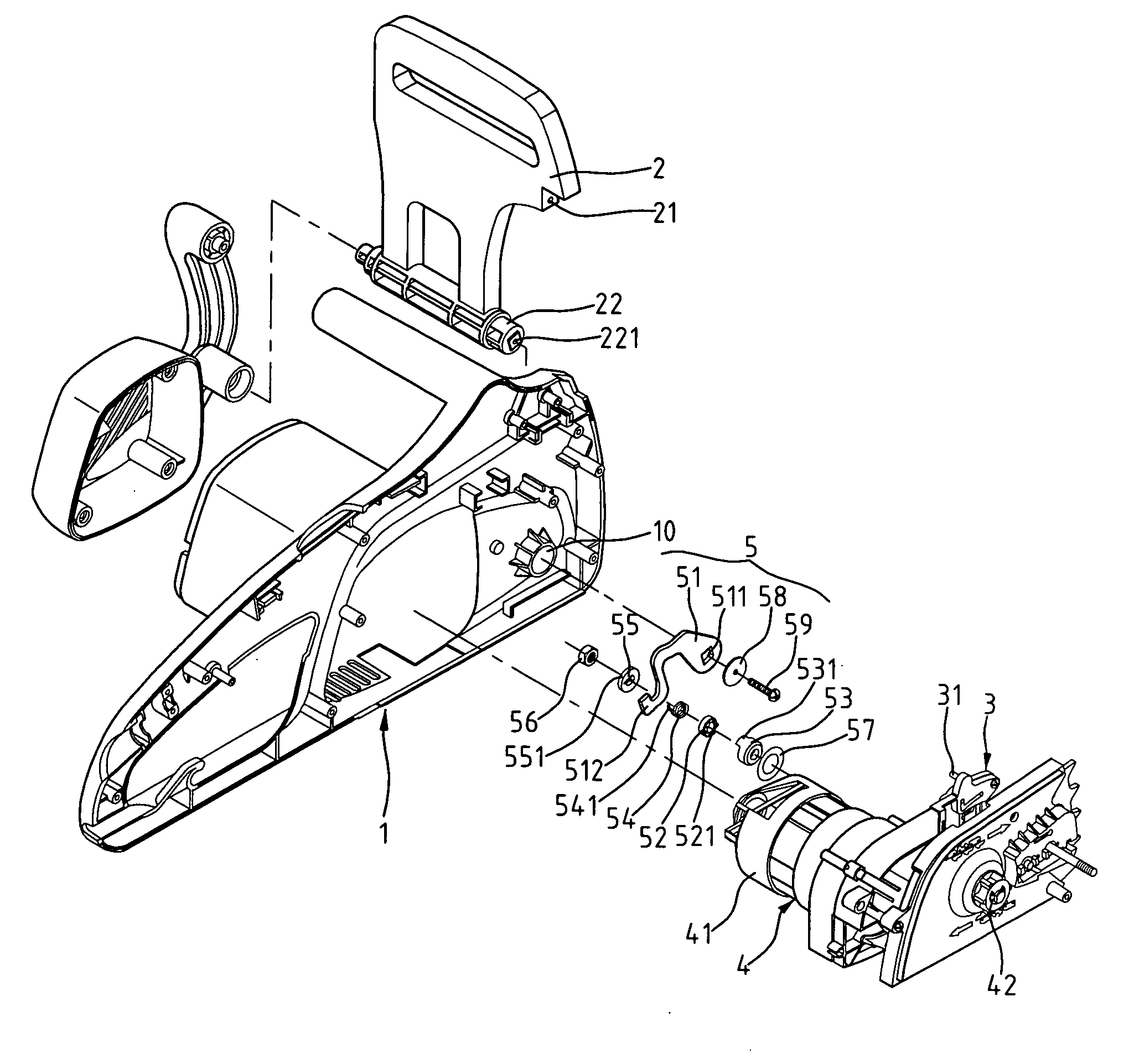
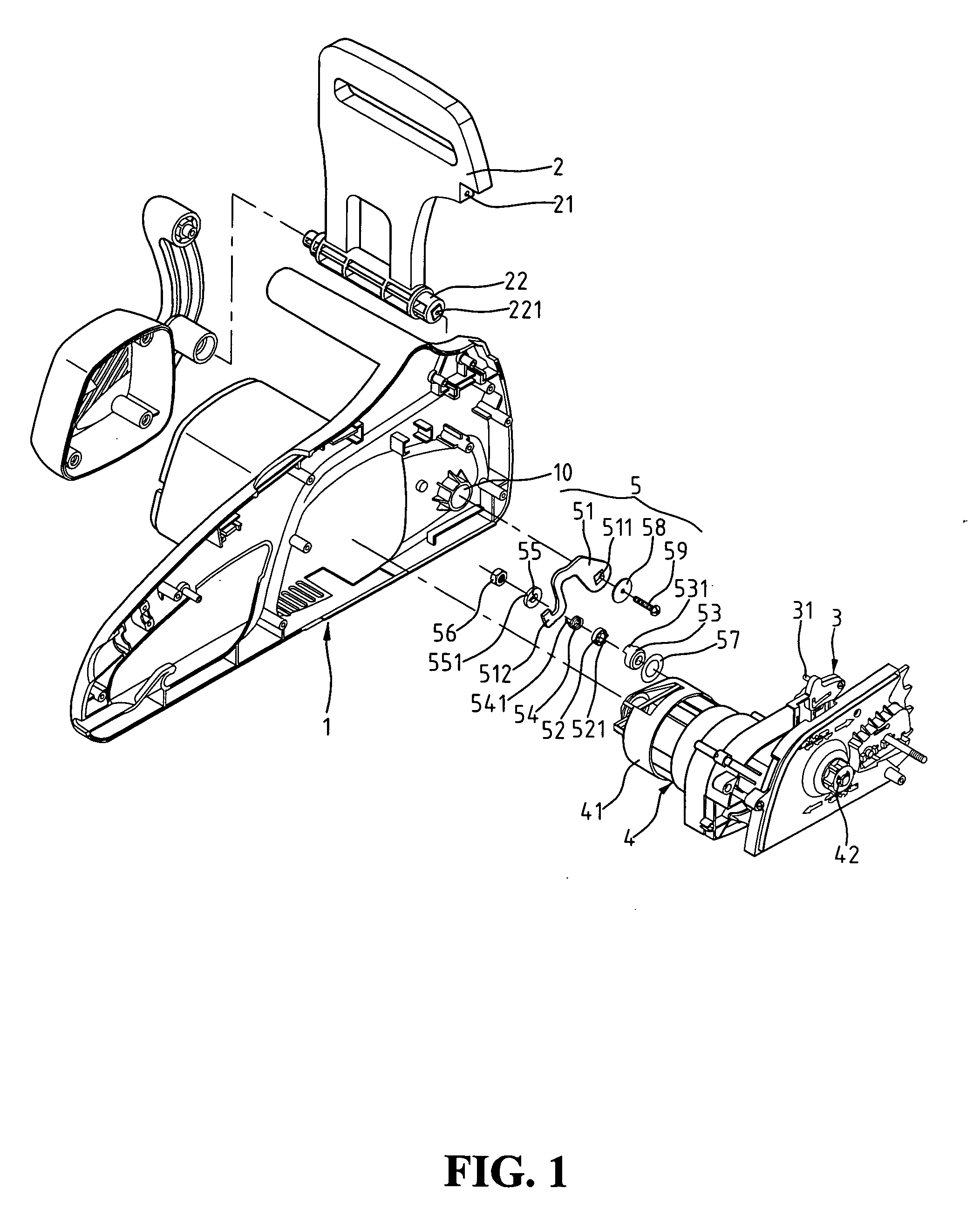
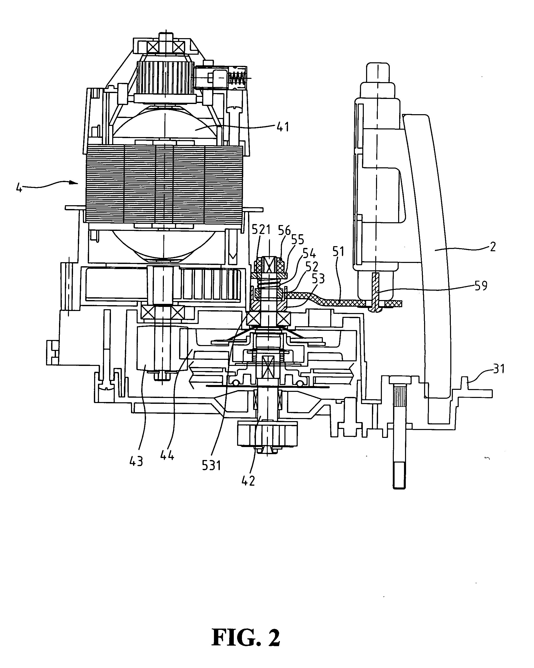
[0015] With reference to the drawings, and in particular to FIGS. 1 and 2, a portion of a power tool, generally designated with reference numeral 1, is shown. The other portion of the power tool is generally not involved in the present invention and is thus omitted in the drawings and will not be described herein. The power tool 1 comprises a power device 4 and a brake assembly 3 arranged inside a case (not labeled) and operatively coupled together. The brake assembly 3 constitutes an emergency shut-down device for the power tool 1. The power device 4 comprises an electrical motor 41 having a spindle (not labeled) that supports and rotates a first gear 43, which in turn drives a mated second gear 44. An output shaft 42 is coupled to and driven by the second gear 44 to transmit torque to a cutter mounted or otherwise coupled to the output shaft 42.

[0016] A push plate 2, serving as a manual trigger of the shut-down device, comprises a shaft 22 rotatably received in and supported by a...


PUM


Abstract

Disclosed is an emergency shut-down device for a power tool. The shut-down device includes a push plate rotatably mounted to the power tool, a brake assembly for selectively stopping the operation of the power tool and coupled to the push plate so that rotation of the push plate in opposite directions causes actuation and de-actuation of the push plate, and a resistance generation device arranged between the push plate and the power tool. The resistance generation device is operatively coupled to the push plate to induce a predetermined resistance against the rotation of the push plate.

Description

BACKGROUND OF THE INVENTION [0001] 1. Field of the Invention [0002] The present invention relates generally to an emergency shut-down device for power tools, especially power tools for gardening purposes, and in particular to a shut-down device that incorporates a mechanism to eliminate undesired shut-down operation by properly increasing mechanical resistance against manual operation of the shut-down device so as to ensure proper actuation of the shut-down device in emergency cases while eliminating inadvertent actuation / de-actuation of the shut-down device. [0003] 2. The Prior Arts [0004] Gardening tools are usually powered by electrical motors for driving cutters to trim plants and mow lawns. To protect an operator of the power gardening tools, some power gardening tools are provided with emergency shut-down devices, which cut off power supply of the power tool and brake the rotating or moving cutter of the power tool. [0005] A conventional shut-down device for the power gardenin...

Claims


Application Information

Patent Timeline
Patent Type & Authority Applications(United States)
IPC IPC(8): F16P3/00
CPCB27B17/083
Inventor LEE, HSIN-CHIH CHUNG
Owner LEE HSIN CHIH CHUNG
Learn More