Dispensing of multiple volatile substances

a technology of volatile substances and dispersing devices, applied in the direction of separation processes, instruments, applications, etc., can solve the problem of difficult control of the resultant overall

Active Publication Date: 2006-08-10
SC JOHNSON & SON INC
View PDF14 Cites 89 Cited by
  • Summary
  • Abstract
  • Description
  • Claims
  • Application Information

AI Technical Summary

Benefits of technology

[0016] In yet another preferred embodiment of our invention, a volatile substance dispensing system includes at least one electromechanical dispenser, at least one reading device, and a microprocessor. Each electromechanical dispenser is configured to dispense a volatile substance from a replaceable volatile substance reservoir when the reservoir is loaded in the volatile substance dispensing system. The reservoir includes information relating to the type of volatile substance contained therein. Each reading device reads the information from the reservoir relating to the type of volatile substance stored therein. The microprocessor controls the electromechanical dispenser to emit a volatile substance from the reservoir, with the microprocessor receiving one or more signals from the reading device relating to the information read from the reservoir. The microprocessor then controls the emission of a volatile substance from the reservoir based on the one or more signals received from the reading device.
[0017] In another preferred embodiment of our invention, a volatile substance dispensing system includes at least one electromechanical dispenser, at least one reading device, and a microprocessor. Each electromechanical dispenser is configured to dispense a volatile substance from at least one replaceable volatile substance reservoir, respectively, when the reservoir is loaded in the volatile substance dispensing system. In this embodiment, the reservoir includes information relating to one or more computer-readable programs. Each reading device reads the information from the fragrance reservoir. The microprocessor receives signals from the reading device communicating the information relating to one or more computer-readable programs and controls the at least one electromechanical dispenser to emit a volatile substance from the reservoir in accordance with the signals communicated from the reading device.

Problems solved by technology

The known fragrance delivery devices, however, are generally constructed independently and it is difficult to control the resultant overall effect when several of these devices are used in the same room or area.

Method used


Image

  • Dispensing of multiple volatile substances
  • Dispensing of multiple volatile substances
  • Dispensing of multiple volatile substances

Examples


Embodiment Construction

General Configurations

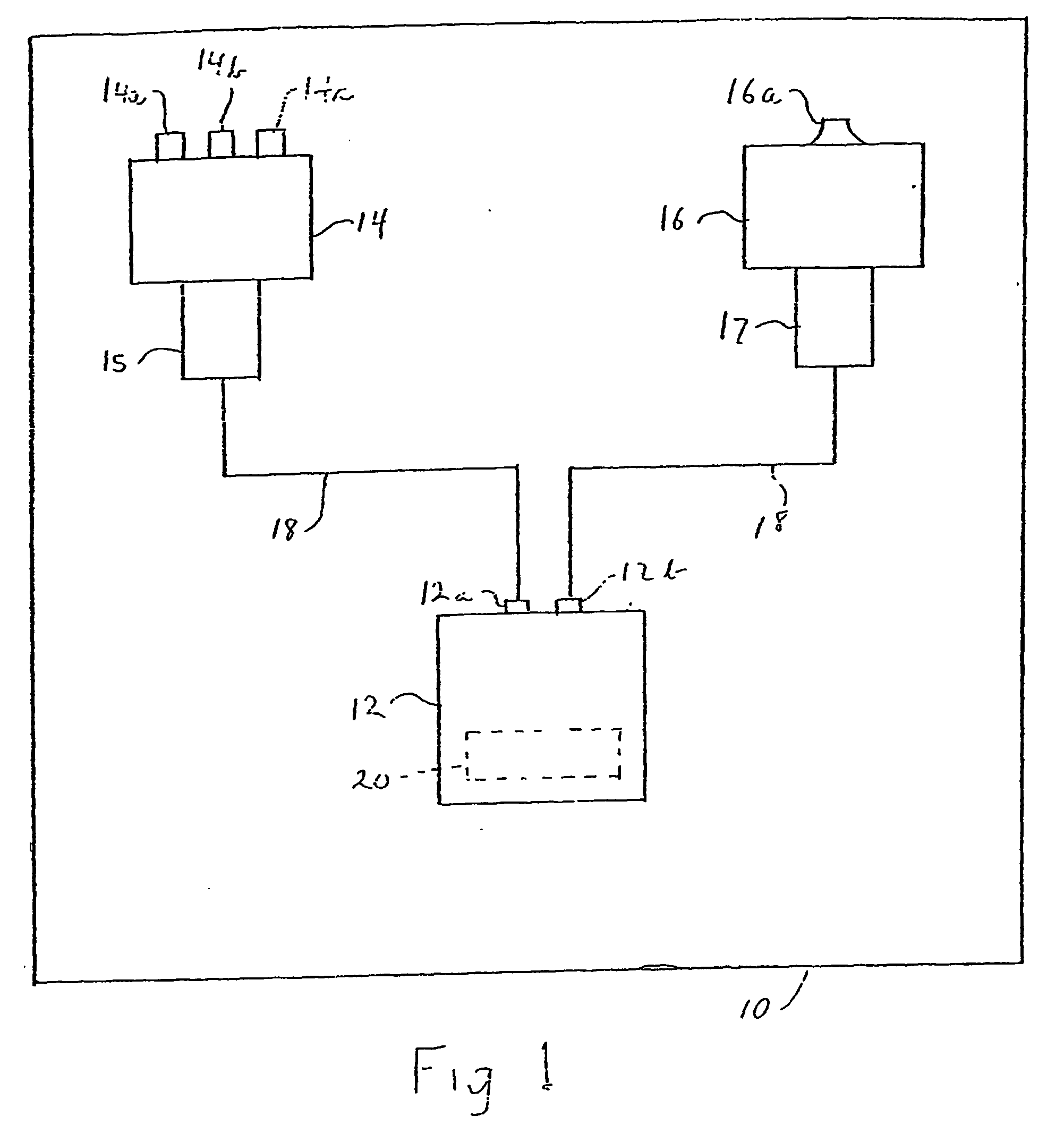
[0031] As shown in FIG. 1, there is provided in a room 10, or other area such as a yard, a processor 12, a luminescent device 14 and a dispenser 16, for emitting a volatile substance (while any one of a number of volatile substances may be used, fragrances and insecticides will generally be discussed below for exemplary purposes). The luminescent device 14 is a light emitting device, and it may comprise a device that emits visible light or light for illumination. In a preferred arrangement, the luminescent device 14 includes light emitting diodes (LED's) 14a, 14b and 14c which emit light in different colors, respectively.

[0032] The dispenser 16 may be a mechanical atomization device such as shown and described in U.S. Pat. No. 6,292,196. In such a case, a fragrance (or insecticide), preferably, is supplied in liquid form to the dispenser and is atomized in the dispenser by any of various controllable means, for example, by an orifice plate that is vibrated b...


PUM

PropertyMeasurementUnit
volatileaaaaaaaaaa
humidityaaaaaaaaaa
temperatureaaaaaaaaaa

Abstract

A method and apparatus for controlling emission of fragrances into a given area such as a room or a region of a yard; and more particularly the creation of a desired atmosphere within the given area. In addition, the invention involves a volatile substance dispensing device (200) having mounted therein a plurality of reservoirs (31) storing a volatile substance, and a plurality of atomizer assemblies (34) for emitting volatile substances communicated thereto by the reservoirs (31). Preferably, a microcontroller (50) controls the emission of the volatile substances in accordance with preferred programs.

Description

BACKGROUND OF THE INVENTION [0001] 1. Field of the Invention [0002] Our invention relates to the controlled and coordinated emission of volatile substances (preferably fragrances and / or insecticides) into a given area such as a room or a region of a yard; and more particularly it concerns the creation of a desired atmosphere within the given area. In addition, our invention involves various means for providing instructions to a microcontroller / microprocessor to control the emission of volatile substances. Further, the emission of volatile substances, preferably fragrances, may be coordinated with the emission of light. [0003] 2. Description of the Related Art [0004] There are known devices for controlling the atmosphere through the release of fragrance. U.S. Pat. No. 5,382,410 discloses an electrostatic vapor / aerosol generator for supplying aromatic oil, deodorant, disinfectant, fumigant, fungicide, insecticide or bactericide to a room. U.S. Pat. No. 4,702,418 discloses an adjustabl...

Claims


Application Information

Patent Timeline
Patent Type & Authority Applications(United States)
IPC IPC(8): A01G27/00A61L9/03A61L9/12A61L9/14A63H33/40B05B17/06H01L27/108
CPCA01M1/2033A01M1/2038A01M1/205A01M1/2077A61L9/035A61L9/037A61L9/122A61L9/125A61L9/127A61L9/14A61L2209/12A63H33/40B05B17/0646B05B17/0684
Inventor SCHRAMM, HEATHER R.WALTER, SCOTT D.JAWORSKI, THOMASHELF, THOMAS A.PORCHIA, JOSEMARTENS, EDWARD J. IIITOMKINS, DAVID A.
Owner SC JOHNSON & SON INC
Why Eureka
Try Eureka