
Apparatus and methods for controlling position of marine seismic sources

Inactive Publication Date: 2006-08-10
WESTERNGECO LLC
View PDF12 Cites 49 Cited by
  • Summary
  • Abstract
  • Description
  • Claims
  • Application Information

AI Technical Summary

Benefits of technology

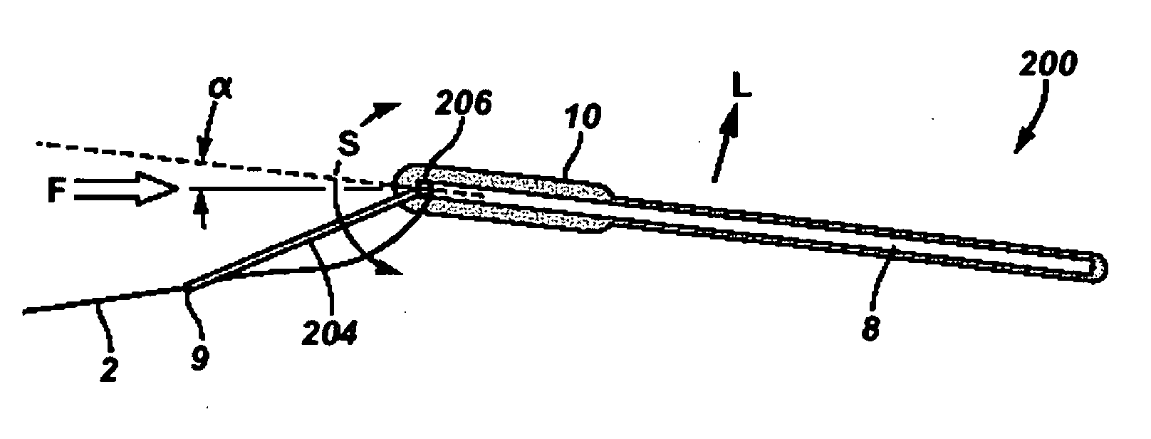
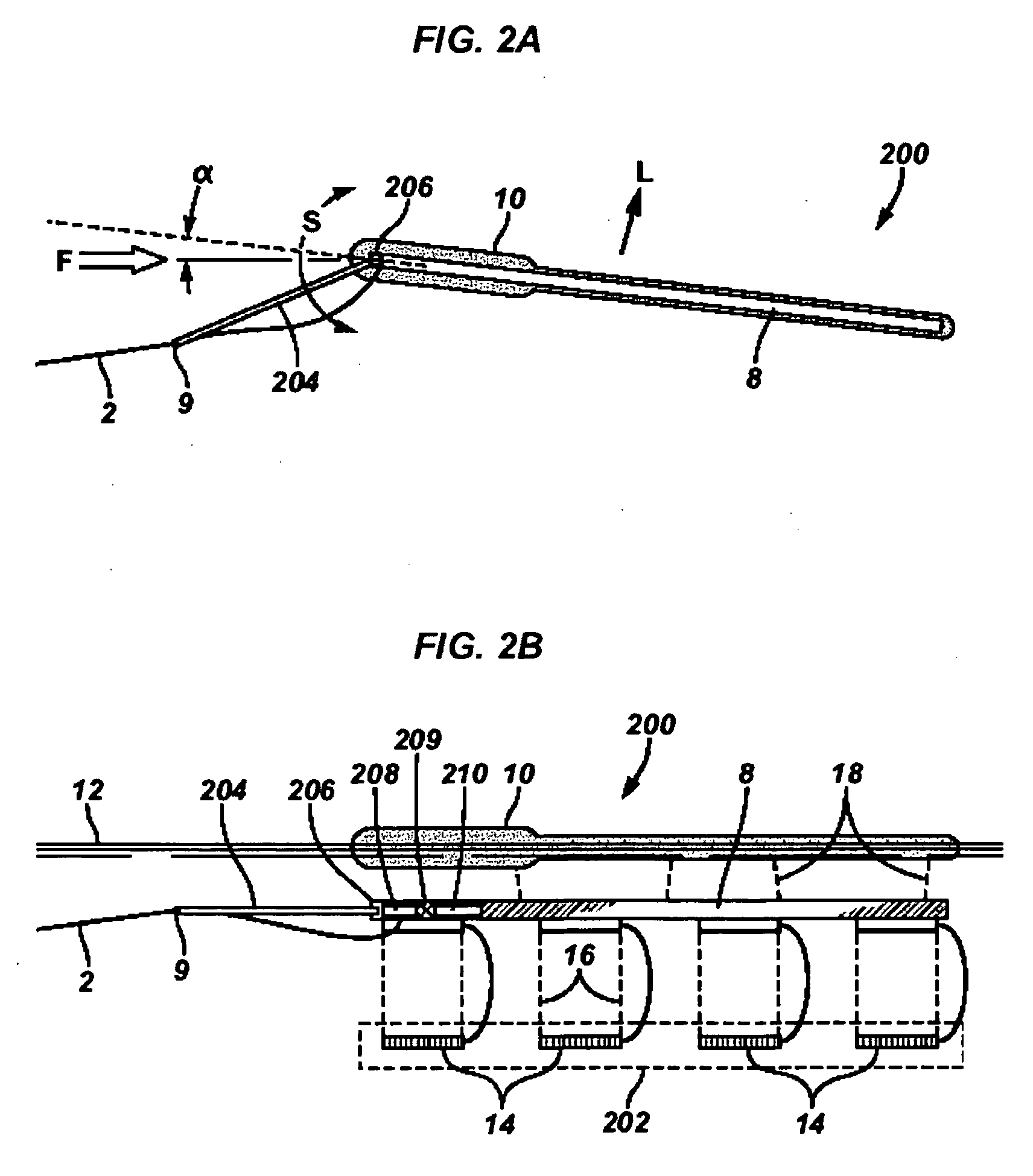
[0013] In accordance with the present invention, apparatus, systems and methods are described for actively controlling position of marine seismic sources and source arrays that reduce or overcome problems with previous apparatus and methods. Apparatus and systems of the invention comprise a source array, sometimes referred to herein as a gun-array, the source array comprising one or more source members, sometimes referred to herein as air-guns. As used herein the term “source array” is meant to be broader than the term gun-array, which those skilled in the art will recognize as meaning one or more air-guns. The term “source member” is meant to be broader than the term air-gun, and is meant to include all acoustic sources, including, but not limited to, air-guns, oscillating members, vibration members, explosive charges, percussion devices, and the like. Thus, in the same way that a gun-array includes one or more air-guns, a source array comprises one or more source members. The terms gun-array,

Problems solved by technology

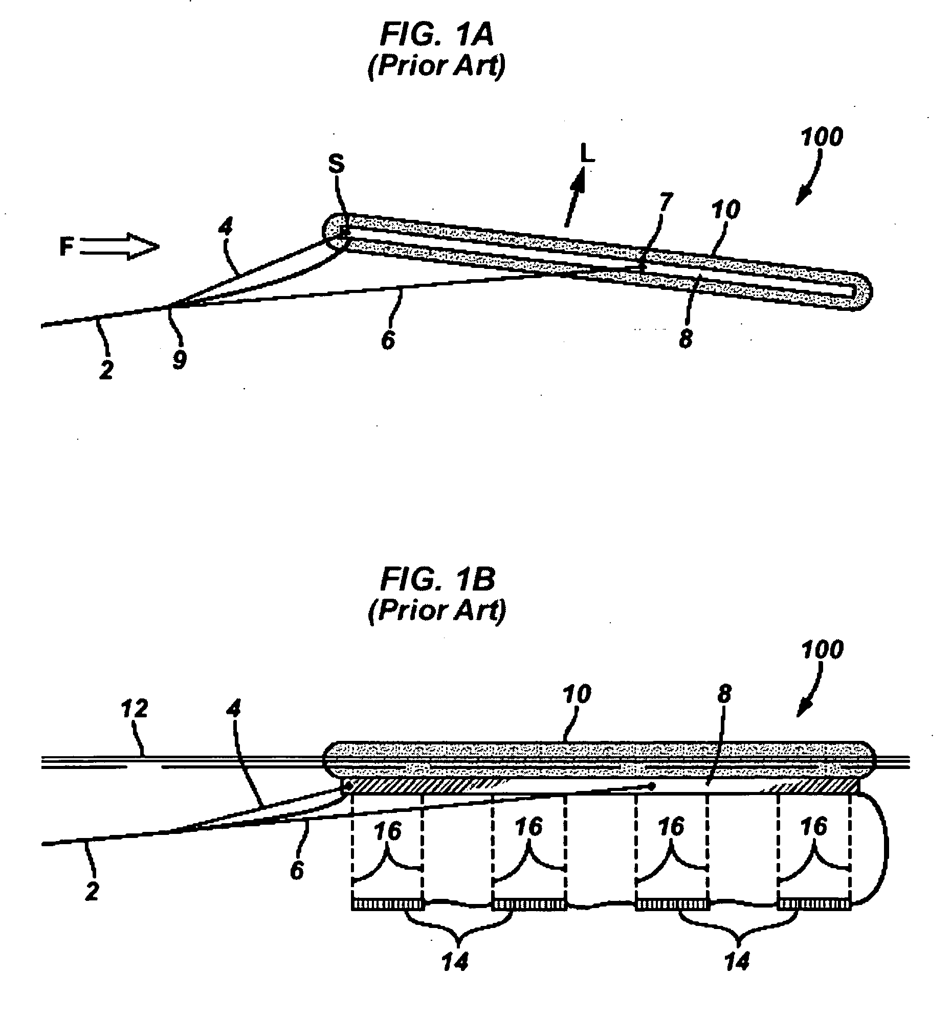
This has been difficult to accomplish in a marine survey because the acoustical source members are typically towed behind the tow vessel in source arrays, which are subject to wave and current movement.
In addition to the deployment and operation difficulties associated with towing multiple streamers and / or multiple source arrays, conventional techniques limit the ability to position source arrays and streamers in different relative positions and orientations.
Source array design is limited by the tow configuration.
Each towed source array is also subject to crosscurrents, wind, waves, shallow water, and navigation obstacles that limit the coverage provided by the survey system.
However, this method and apparatus offers no possibilities for remotely adjusting the angle of attack.
The previous attempts have not provided optimal control of the location of the source arrays under towing conditions.

Method used


Image

  • Apparatus and methods for controlling position of marine seismic sources
  • Apparatus and methods for controlling position of marine seismic sources
  • Apparatus and methods for controlling position of marine seismic sources

Examples


Embodiment Construction

[0045] In the following description, numerous details are set forth to provide an understanding of the present invention. However, it will be understood by those skilled in the art that the present invention may be practiced without these details and that numerous variations or modifications from the described embodiments may be possible.

[0046] The present invention relates to various apparatus, systems and methods for controlling position of one or more marine seismic components. The terms “controlling position”, “position controllable”, “remotely controlling position”, “remotely adjustable”, and “steering” are generally used interchangeably herein, although it will be recognized by those of skill in the art that “steering” usually refers to following a defined path, while “controlling position”, “position controllable”, and “remotely controlling position” could mean steering, but also could mean merely maintaining a relative position, for example relative to one or more reference...


PUM


Abstract

Apparatus and methods are described for remotely controlling position of marine seismic equipment. One apparatus comprises a source connected to a tow member; and an adjustment mechanism connected to the source and the tow member, the adjustment mechanism adapted to actively manipulate an angle of attack of the source. It is emphasized that this abstract is provided to comply with the rules requiring an abstract, which will allow a searcher or other reader to quickly ascertain the subject matter of the technical disclosure. It is submitted with the understanding that it will not be used to interpret or limit the scope or meaning of the claims. 37 CFR 1.72(b).

Description

BACKGROUND OF THE INVENTION [0001] 1. Field of Invention [0002] The present invention relates to the field of marine seismic instruments and methods of controlling same. More specifically, the invention relates to apparatus and methods for remotely controlling position marine seismic instrumentation, as well as related systems, methods, and devices. [0003] 2. Related Art [0004] Marine seismic exploration investigates and maps the structure and character of subsurface geological formations underlying a body of water. For large survey areas, a single vessel may tow one or more seismic sources and one or more seismic streamer cables through the water. Alternatively, a tow vessel may either be a “pure” source vessel (meaning it only tows seismic sources) or a “pure” streamer (receiver) vessel, in which case two or more vessels may be used. In any case the seismic sources may comprise compressed air guns or other means for generating acoustic pulses in the water. The energy from these pu...

Claims


Application Information

Patent Timeline
IPC IPC(8): G01V1/38
CPCG01V1/3861B63B21/66G01V1/3817
Inventor TOENNESSEN, RUNE
Owner WESTERNGECO LLC
Learn More