Combination pile wall

a pile wall and combination technology, applied in the field of combination pile walls, can solve the problems of affecting the vertical affecting the stability and stiffness of the overall combination pile wall, and disengaged locking elements

Inactive Publication Date: 2006-08-17
SHEET PILE LLC
View PDF20 Cites 19 Cited by
  • Summary
  • Abstract
  • Description
  • Claims
  • Application Information

AI Technical Summary

Benefits of technology

[0004] A principal object of the present invention is to provide a combination pile wall that ensures exact positioning of the individual components while maintaining adequate vertical stability and water sealing characteristics.

Problems solved by technology

The problem with known combination pile walls is that the locking elements engaged with one another are either so manufactured that they may hardly move with respect to one another, or the locking elements are so shaped that they may pivot over a wide angular range of up to ±45°.
If the individual beam elements between which sheet piles are positioned as necessary are driven into the ground, there is a danger that, for those joints in which the locking elements allow practically no movement with respect to one another, the locking elements will become disengaged at least in sections or that the joints will break completely.
On the one hand, this causes the vertical stability and stiffness of the overall combination pile wall to be negatively influenced while, on the other, it allows passage of water through the combination pile wall because the sections are damaged or are no longer engaged.
If, in contrast, combination pile walls are used where the locking elements allow large pivot angles, the beam elements and sheet piles may deviate from each other when driven into the ground, moving out of their intended positions, so that an exact positioning of the combination pile wall is made more difficult.

Method used


Image

  • Combination pile wall
  • Combination pile wall
  • Combination pile wall

Examples


Embodiment Construction

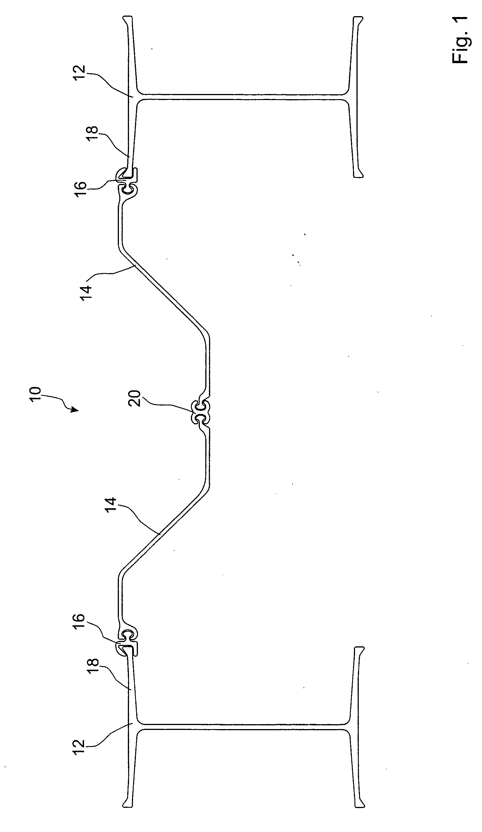
[0026] The preferred embodiments of the present invention will now be described with reference to FIGS. 1-5 of the drawings. Identical elements in the various figures are designated with the same reference numerals.

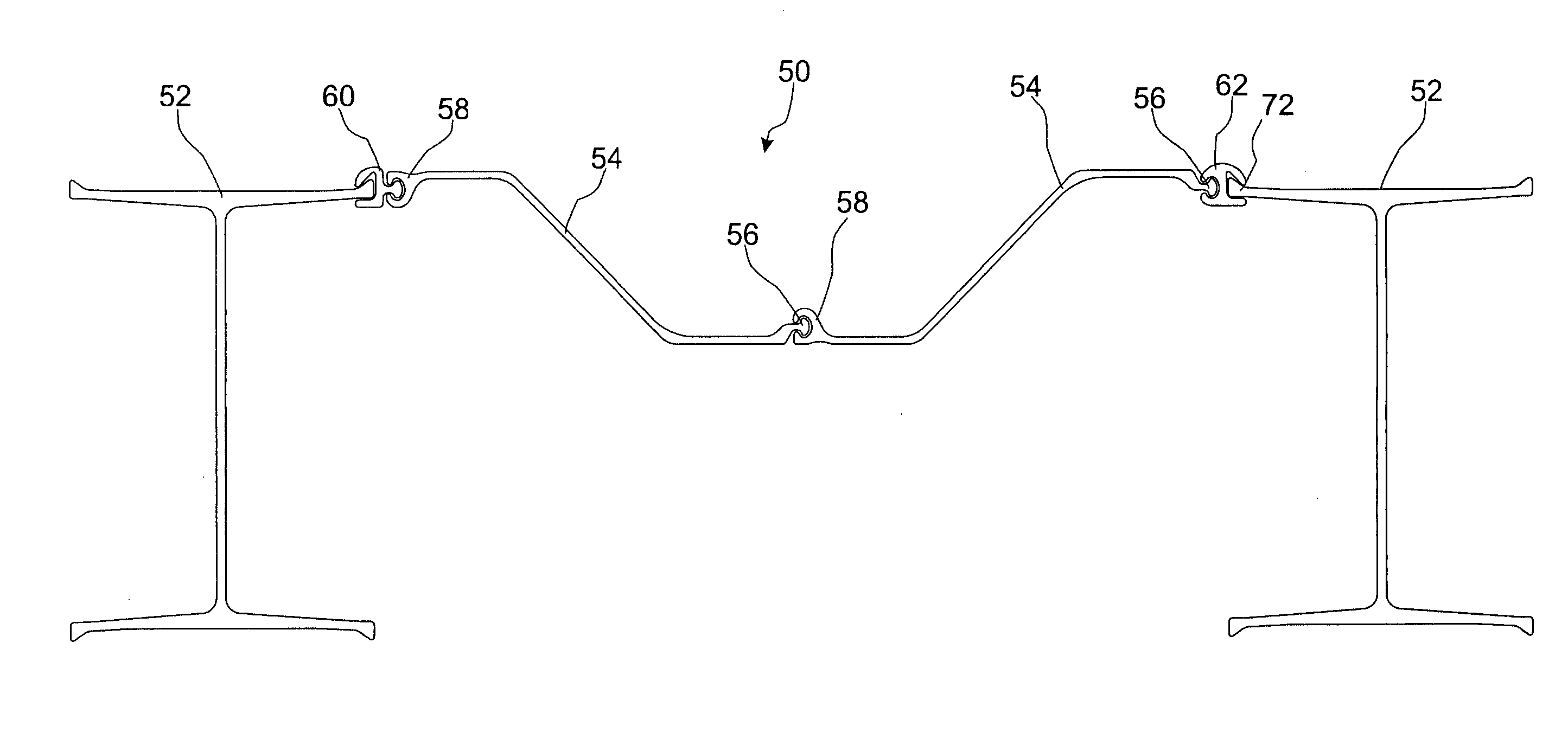
[0027]FIG. 1 shows a top view of a first embodiment of a wall section of a combination pile wall 10 according to the invention. The combination pile wall 10 in this case is formed of two claimed beam carriers 12 between which two Z-shaped sheet piles 14 are inserted. Instead of the two Z-shaped sheet piles coupled together, a single U-shaped sheet pile may, for example, be used. A shaped connection strip 16 is positioned between each sheet pile 14 and each beam carrier 12 with one end of its two T-beams 18 and the sheet pile 14 suspended by their longitudinal edges. The two other longitudinal edges of the sheet piles 14 are hung on one common central slide lock 20. Both the shaped connection strip 16 and the central slide lock 20 possess a constant cross section, and are...


PUM


Abstract

A combination pile wall is formed of beam elements (12), particularly T-beams and double-T-beams (I-beams), and shaped connection strips (16) directly or indirectly connecting the beam elements (12), whereby each shaped connection strip (16) that is coupled directly with one of the beam elements (12) is engaged with one of the locking elements (30) formed on the respective beam element (12). The two mutually-engaged locking elements (24, 26) of the shaped connection strip (16) and of the beam element (12) are configured with a cross section such that the two locking elements (24, 26) may pivot with respect to each other through an angular range of a minimum ±3° to a maximum ±10°.

Description

BACKGROUND OF THE INVENTION [0001] The invention concerns a combination pile wall, and more particularly a pile wall comprising a plurality of adjacent pile wall beam elements interconnected by connecting elements and possibly also sheet pile elements. [0002] Combination pile walls of the aforesaid type are known from DE 297 18 052 U1, EP 0 072 118 A1, or also DE 103 18 769 A1; they are used to reinforce banks of harbors and rivers, to support a dam, or to erect quay walls and the like. The known combination pile walls are formed of beam elements such as double-T beams (I-beams), with connection shaped strips (connecting elements) connected directly to them which are intended to ensure at least an approximately watertight seal between the beam elements. The shaped connection strips are equipped with locking elements that engage with matching locking elements on the beam elements. If the loads on the combination pile walls from the soil are moderate, at least one sheet pile, called a...

Claims


Application Information

Patent Timeline
Patent Type & Authority Applications(United States)
IPC IPC(8): E04B2/00
CPCE02D5/04E02D5/06
Inventor HEINDL, RICHARDWENDT, ROB. R.WALL, GEORG
Owner SHEET PILE LLC
Why Eureka
Try Eureka