
Optical element washing apparatus

a technology of washing apparatus and optical elements, applied in the field of washing apparatuses, can solve the problems of low efficiency of optical element washing apparatus, inability to wash large numbers of art washing apparatus, and inability to wash lenses one by one, so as to increase high washing efficiency, and the effect of increasing the exposed area of optical elements

Inactive Publication Date: 2006-08-17
HON HAI PRECISION IND CO LTD
View PDF23 Cites 7 Cited by
  • Summary
  • Abstract
  • Description
  • Claims
  • Application Information

AI Technical Summary

Benefits of technology

[0008] The plurality of clamping poles with the plurality of V-shaped grooves are used for holding a plurality of optical elements at a time. Therefore, the optical element washing apparatus has high washing efficiency and can be used in washing optical elements in mass quantities. In addition, the V-shaped grooves of the clamping poles can increase the exposed area of the optical elements so that the optical elements can be washed even more effectively.

Problems solved by technology

However, the optical element washing apparatus can only wash lenses one by one.
Therefore, the efficiency of the optical element washing apparatus is low, and this prior art washing apparatus is not practical for washing large numbers of optical elements within a short period of time.

Method used


Image

  • Optical element washing apparatus
  • Optical element washing apparatus
  • Optical element washing apparatus

Examples


Embodiment Construction

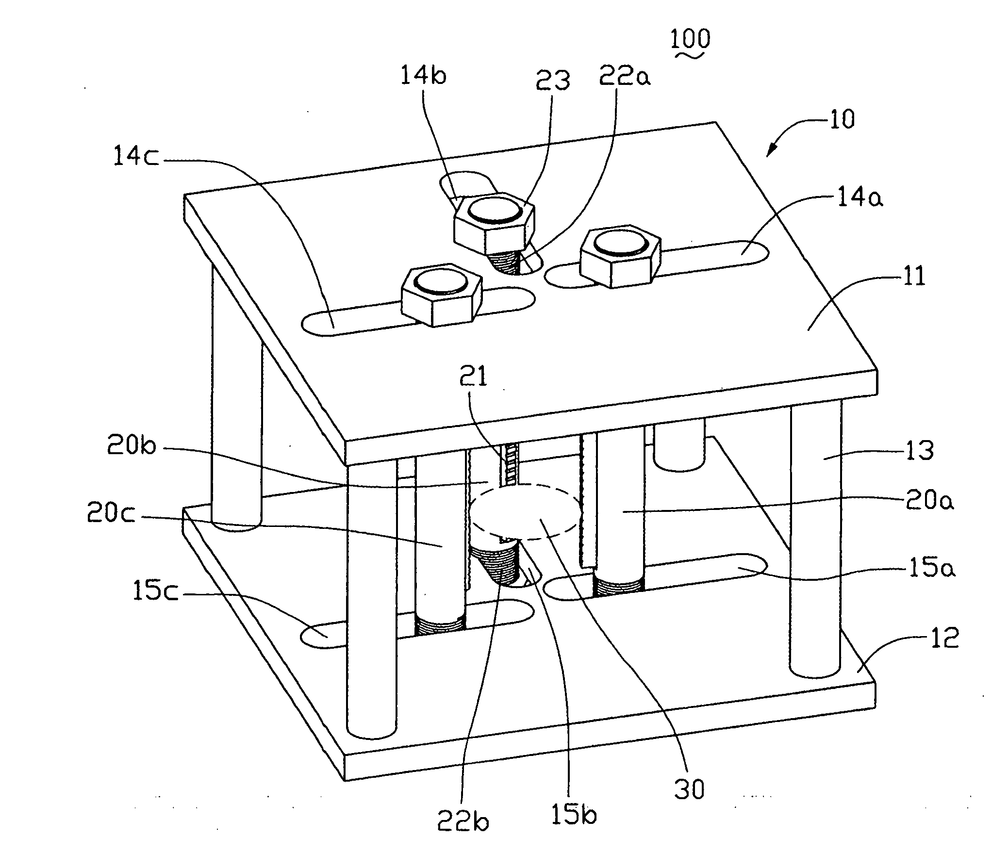
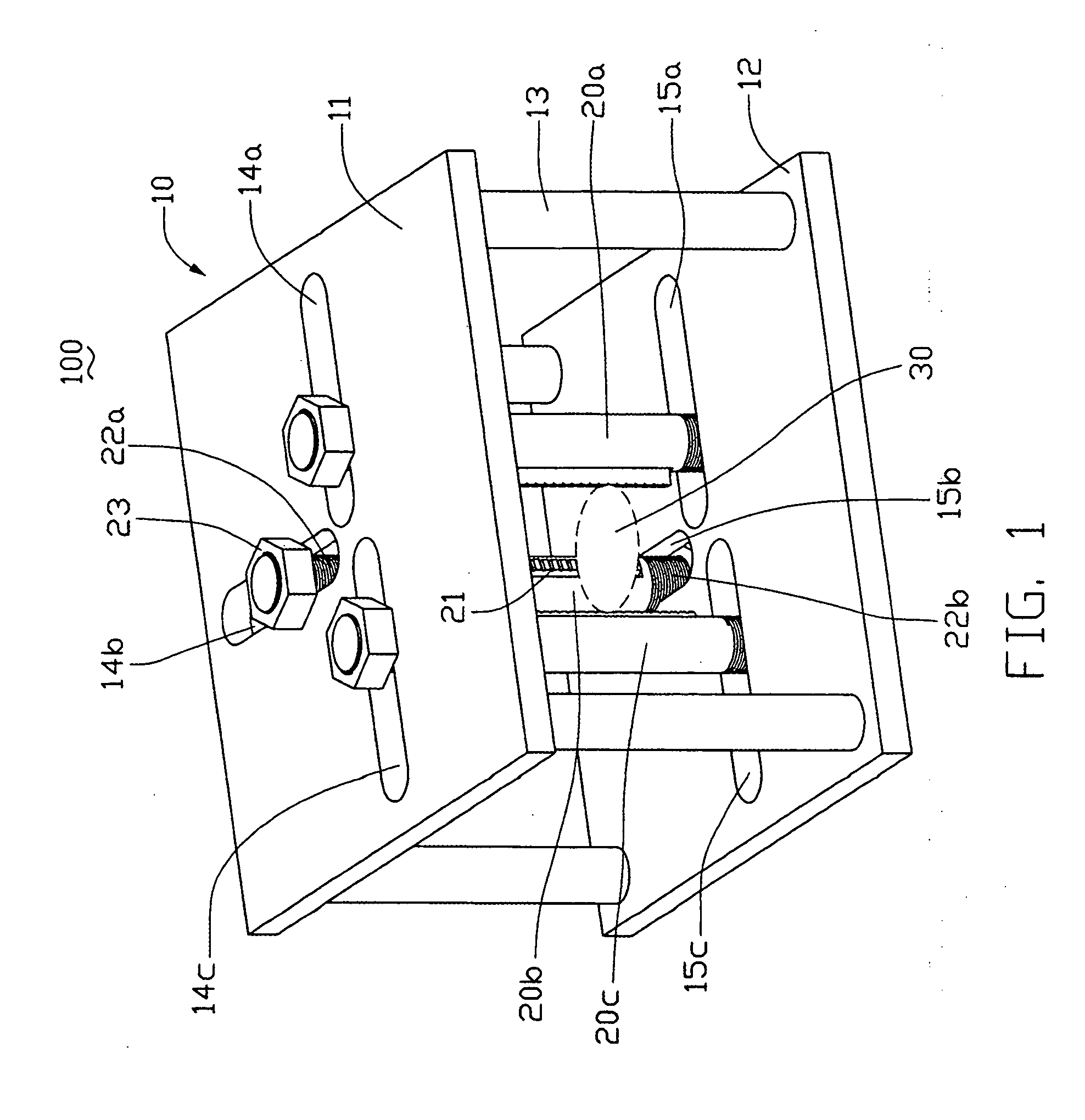
[0014] Referring to FIG. 1, in a preferred embodiment, an optical element washing apparatus 100 includes a holding frame 10, a plurality of clamping poles 20a, 20b, 20c, and a plurality of nuts 23.

[0015] The holding frame 10 incorporates a top board 11, a bottom board 12, and a plurality of holding poles 13. The top board 11 and the bottom board 12 are advantageously rectangular or square, as such shapes promote a close packing of multiple holding frames in a given space. The holding poles 13 are provided between the top board 11 and the bottom board 12 and are configured for holding the two boards 11, 12 at a desired spacing. The top board 11 defines three guiding slots 14a, 14b, 14c. Each guiding slot 14a, 14b, 14c is strip shaped and are arrayed in a T-shape. Corresponding to the three guiding slots 14a, 14b, 14c, the bottom board 12 also defines three guiding slots 15a, 15b, 15c. It is to be understood, however, that each board 11, 12 could have other corresponding numbers and ...


PUM


Abstract

An optical element washing apparatus (100) includes a holding frame (10) and a plurality of clamping poles (20a, 20b, 20c). The holding frame includes a top board (11) and a bottom board (12), and each of the top board (11) and the bottom board (12) has a plurality of guiding slots (14a, 14b, 14c; 15a, 15b, 15c) formed therethrough. Each clamping pole has a plurality of V-shaped grooves (21) defined therein. The clamping poles, in part, extend through the guiding slots and can be moved along at least one of the guiding slots and connected with the holding frame. The plurality of clamping poles, together with the V-shaped grooves, are used for holding a plurality of optical elements at a time. Therefore, the optical element washing apparatus has a high washing efficiency and can be used in washing batches of optical elements.

Description

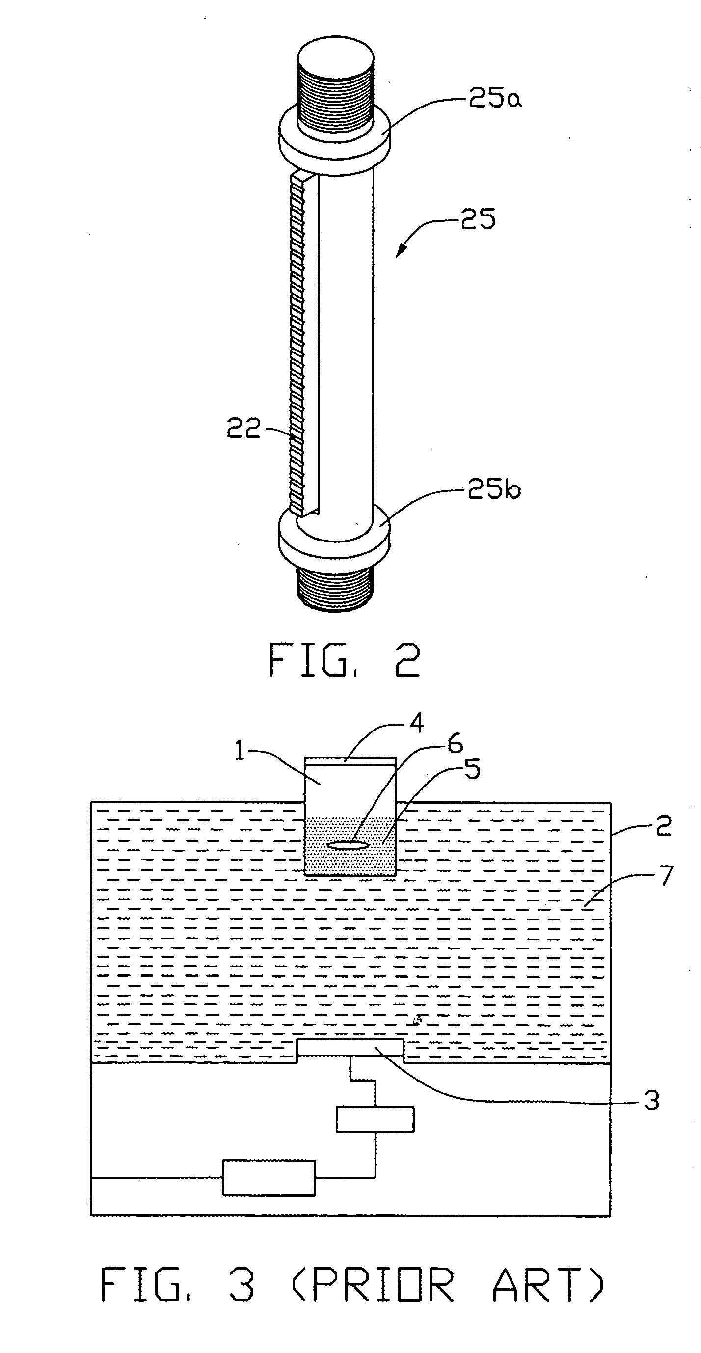
BACKGROUND OF THE INVENTION [0001] 1. Field of the Invention [0002] The present invention relates to washing apparatuses and, in particular, to an optical element washing apparatus for cleaning lenses. [0003] 2. Discussion of the Related Art [0004] Nowadays, optical elements such as lenses are commonly used in digital cameras or digital video recorders. There is more and more demand for higher quality and serviceability of these optical elements. A film such as an antireflective film or an infra-red cut film is generally plated on the optical elements, especially on lenses. To improve imaging quality, it is an important first step to wash the optical elements before plating a film thereon. How to wash optical elements effectively before plating is an important technology. [0005] Usually, optical elements are washed by a concussion of ultrasonic waves in a vessel filled with liquid. For example, referring to FIG. 3, P.R. China Patent No. 99234336.4 discloses an optical element washin...

Claims


Application Information

Patent Timeline
Patent Type & Authority Applications(United States)
IPC IPC(8): G02B27/44
CPCG02B27/0006
Inventor YEN, SHIH-CHIEN
Owner HON HAI PRECISION IND CO LTD
Learn More