
Connector for memory card

a technology for connecting devices and memory cards, applied in the direction of coupling devices, two-part coupling devices, electrical apparatus, etc., can solve the problems of insufficient operation, card may bounce out of the housing with great force, memory card damage, etc., and achieve the effect of reducing the force and preventing the bounce out of memory cards

Inactive Publication Date: 2006-08-17
MATSUSHITA ELECTRIC WORKS LTD
View PDF8 Cites 27 Cited by
  • Summary
  • Abstract
  • Description
  • Claims
  • Application Information

AI Technical Summary

Benefits of technology

[0012] A first object of the present invention is to provide a connector for memory card which can ensure stability in contact even when bending dimension of the movable spring piece varies. A second object of the present invention is to provide a connector for memory card which can prevent bounce-out of the memory card.
[0014] By such a configuration, in spite of positional variation of the movable spring piece, the inclined plane provided on the movable spring piece comes into contact with the fixed contact plate at two points, so that it is possible to stabilize the contact state between the fixed contact and the elastic contact portion.
[0015] In addition, by further comprising: a pressing spring for pressing said slider in a direction of taking out the memory card; a push-on and push-off locking mechanism that locks movement of said slider when said slider is moved to a locking position inner than a position at which the terminals of the memory card come into contact with said contacts, and releases the locking of said slider when said slider is moved to a lock releasing position inner than the locking position; and elastic protrusions provided in portions where concave portions for locking formed on the memory card pass while a front end of said slider moves to the initial position after the terminals of the memory card are departed from said contacts when the memory card is taken out, the elastic protrusions engage with the concave portions for locking just before the slider and the memory card return to the initial position, so that it is possible to reduce a force to push out the memory card rapidly and reliably by elastic force of the elastic protrusions. As a result, the bounce-out of the memory card can be prevented.

Problems solved by technology

When the pressing force of the pressing spring is too strong, the memory card may bounce out from the housing with great force, and the memory card may be damaged due to falling.
On the contrary, when the pressing force of the pressing spring is too weak, the pressing force may become weaker than frictional force caused by contact pressure of the contacts against the terminals of the memory card or the like, so that the slider and the memory card engaged therewith may be stopped before departing the terminals of the memory card from the contacts, resulting insufficient operation.

Method used


Image

  • Connector for memory card
  • Connector for memory card
  • Connector for memory card

Examples


first embodiment

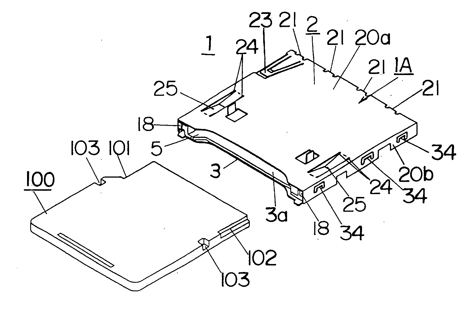
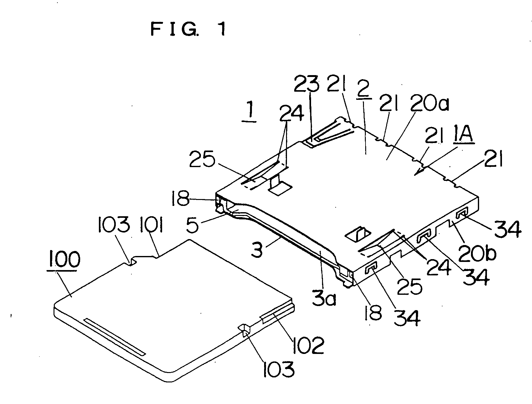
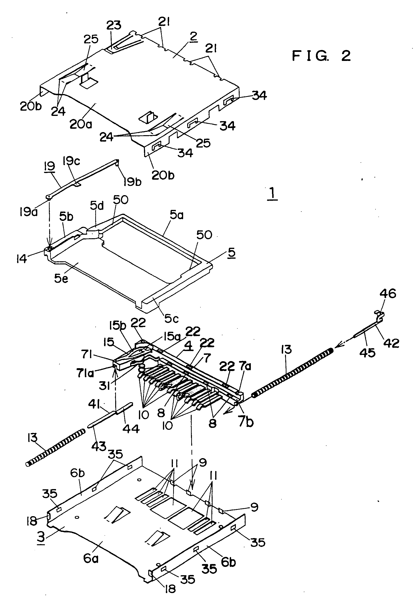
[0029] A connector for memory card in accordance with a first embodiment of the present invention will be described in detail with reference to figures. In the following description, the side of a card insertion slot of a housing of the connector is defined as “front” and the side on which contacts are provided is defined as “rear”. With respect to the memory card, the side that protrudes from the housing of the connector is defined as “rear” and the side on which terminals and a chamfered portion are formed is defined as “front”. In addition, with respect to the housing, the side of a cover shell is defined as “upper” and the side of a base shell is defined as “lower”.

[0030] First, a mini SD card as an example of the memory card will be described briefly. A memory card 100 shown in FIG. 1 is called as the mini SD card, which is a miniaturized version of a conventional SD memory, is shaped as a substantially rectangular flat plate and has a chamfered portion 101 at a corner of a fr...

second embodiment

[0059] Subsequently, a connector for memory card in accordance with a second embodiment of the present invention will be described in detail with reference to figures. Description of parts common to the parts in the above-mentioned first embodiment is omitted.

[0060] In the second embodiment, as shown in FIG. 8 to FIG. 11, plate spring-like elastic protrusions 26 are formed by cutting regions where the recessed portions 103 for locking pass while the slider 5 moves to the initial position at the front end after departing the terminals 104 of the memory card 100 from the contacts 10, on the top plate 20a of the cover shell 2, when the memory card 100 is taken out. A front end of the elastic protrusion 26 is connected to the top plate 20a to become a fixed end, and a free end protrudes downward and comes into contact with the top face of the memory card 100.

[0061] By such a configuration, similar to the above-mentioned first embodiment, during the movement of the slider 5 and the mem...


PUM


Abstract

In a connector for memory card, it is objected to stabilize contact of detection switch for detecting insertion of a memory card, and to prevent breakage of the memory card due to bounce-out when it is taken out. The detection switch is held on a contact block with contacts which are to be contacted with terminals of the memory card, and comprised of a fixed contact plate and a movable spring piece. A groove having substantially V-shape is formed on a contacting portion of the movable spring piece so as to contact with the fixed contact plate at two points. Furthermore, elastic protrusions that can fit to recessed portions for locking formed on the memory card just before the slider holding the memory card reaches to an initial position is formed on a top plate of the housing, so that the bounce-out of the memory card is prevented.

Description

TECHNICAL FIELD [0001] The present invention relates to a connector for memory card to which a memory card such as a mini SD card is connected detachably. BACKGROUND ART [0002] As shown in Japanese Patent No. 3252133, for example, this type of connector for memory card comprises a housing on which an opening is provided on a front face so as to insert a memory card therein, a plurality of contacts that is held in the housing and in contact with terminals provided on the memory card, a slider that contacts with the memory card inserted into the housing and is moved along an inserting direction of the memory card into the housing, a pressing spring for pressing the slider in a direction of taking out the memory card, and a push-on and push-off locking mechanism that locks movement of the slider when the slider is moved to a locking position inner than a position at which the terminals of the memory card come into contact with the contacts and releases locking of the slider when the sl...

Claims


Application Information

Patent Timeline
Patent Type & Authority Applications(United States)
IPC IPC(8): H01R24/00H01R13/703
CPCH01R13/7032H01R13/629
Inventor TANAKA, HIROHISAYAMAMOTO, TOSHIHIROKAWASHIMA, MASATO
Owner MATSUSHITA ELECTRIC WORKS LTD
Learn More