Mixture injection port

Active Publication Date: 2006-08-17
JMC
View PDF18 Cites 91 Cited by
  • Summary
  • Abstract
  • Description
  • Claims
  • Application Information

AI Technical Summary

Benefits of technology

[0027] According to the first mixture injection port of the present invention, a circulating path for guiding a fluid to a portion in which a fluid stagnates (septum side) is formed, so that a fluid is circulated to the septum side in which conventionally a fluid was hardly replaced and can be replaced by a new fluid reliably. Therefore, in the channel tube, a fluid is suppressed from stagnating continuously. For example, when used for infusion, blood collection or the like, even if a medical fluid, blood or the like stagnates in the inner cavity of the mixture injection port, the medical fluid or the like can be replaced reliably by a newly transferred fluid. Therefore, an effect of suppressing continuous stagnation of medical fluid, blood or the like can be provided.
[0028] According to

Problems solved by technology

Furthermore, the fact that the medical liquid is hardly replaced i

Method used


Image

  • Mixture injection port
  • Mixture injection port
  • Mixture injection port

Examples


Example

[0048] First, a first embodiment of the present invention will be described.

[0049]

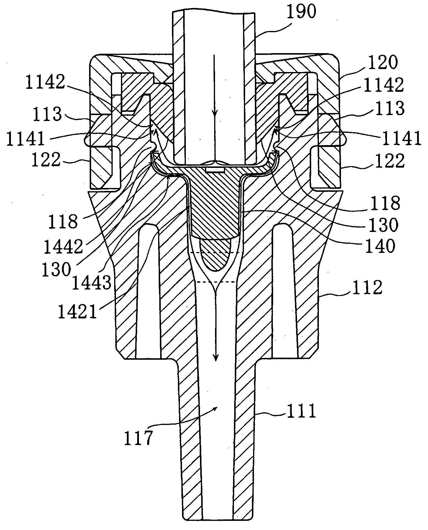
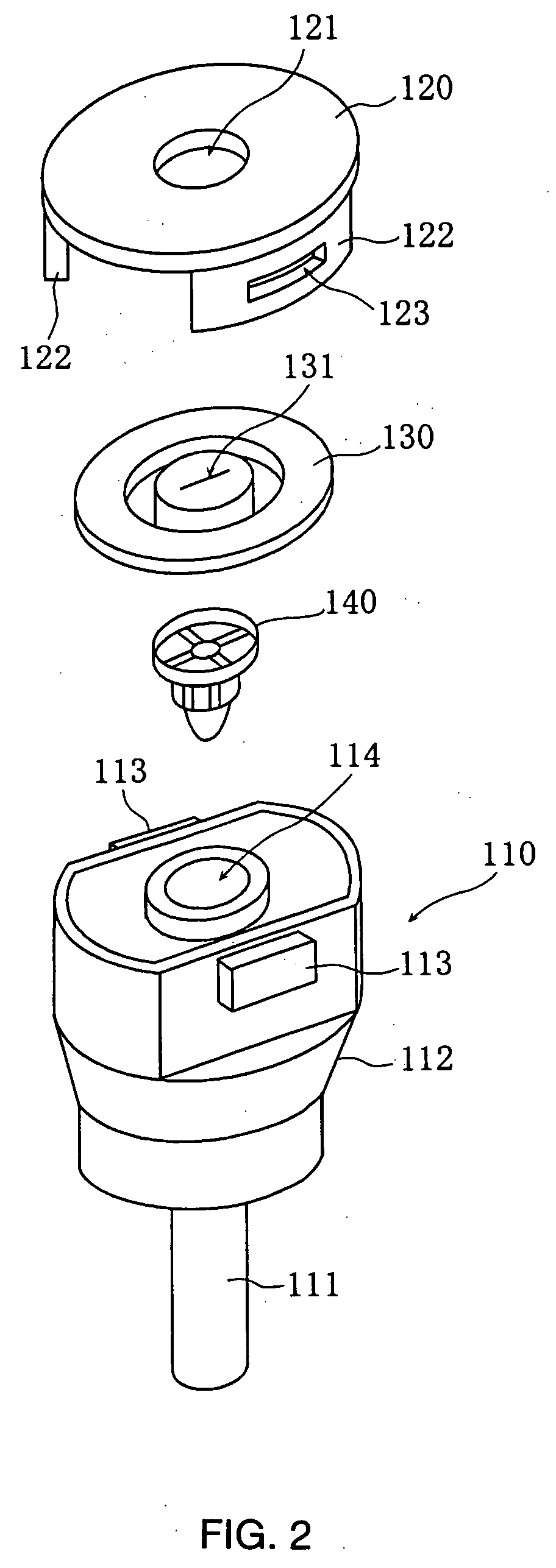
[0050]FIG. 2 is an exploded perspective view of a mixture injection port of a first embodiment of the present invention, and FIGS. 3 and 4 are cross-sectional views of the mixture injection port. In the cross-sectional views referred to in this specification, for easy understanding of the drawings, in some areas, the background of the cross section is not drawn, and only the end face is shown.

[0051] As shown in FIG. 2, the mixture injection port includes a channel tube unit 110, a circulating portion 140, a septum 130, and a cap unit 120. The circulating portion 140 is inserted into the inner cavity 114 of the channel tube unit 110, and the cap unit 120 is engaged with and fixed to one end of the channel tube unit via the septum 130 so that the opening of the inner cavity 114 is sealed.

[0052] As shown in FIG. 2, the channel tube unit 110 includes a leg portion 111 and a body portion 112 and is forme...

Example

Second Embodiment

[0076] In the first embodiment, grooves are formed in a circulating-plate portion in the circulating portion. However, in the second embodiment, the portion in which the grooves are formed and the other portions are reversed. In other words, ribs are formed in the portion in which the grooves were formed, so that a medical fluid can flow between the ribs. The mixture injection port of the second embodiment is different from the mixture injection port of the first embodiment only in the configuration of the circulating portion 140, and therefore different aspects from those in the first embodiment will be primarily described in the following.

[0077]FIG. 6 is a perspective view of a circulating portion 240 of the second embodiment.

[0078] As shown in FIG. 6, the circulating portion 240 includes a circulating-plate portion 241 and a holding portion 242 that is projected from the center of the lower surface of the circulating-plate portion, as in the first embodiment, ...

Example

[0081] One example in which the mixture injection ports of the first and the second embodiments are applied in practice in the medical field will be described. The mixture injection ports of the third and the fourth embodiments, which will be described later, also can be applied to this application example in the same manner.

[0082] For example, when infusing a liquid to a patient, an extension tube is connected to a central venous catheter that is placed in an artery of the patient, and the mixture injection port is connected to the extension tube. The mixture injection port is used in the state where a luer connected to an infusion solution set from an infusion solution bag that is filled with a fat emulsion, a glucide transfusion, an amino acid transfusion or the like is inserted on its septum side. In this case, the infusion solution set is exchanged, for example, every one to four days.

[0083] When the mixture injection port is used in this manner, continuous stagnation of a li...


PUM


Abstract

A mixture injection port is capable of suppressing the continuous accumulation of medical fluid or blood therein and allowing efficient internal cleaning. A recirculation part is formed at a step between an inner cavity and a narrow tube part. Even if the fluid is accumulated in a clearance area produced in the inner cavity when a luer is inserted into a slit, the fluid can be securely replaced with the fluid newly flowing therein through a septum and the continuous accumulation of the fluid can be suppressed. A more efficient internal cleaning can be realized by installing a fluid accumulation prevention part such as an annular rib between the septum and the inside wall of the inner cavity and burying the clearance area.

Description

TECHNICAL FIELD [0001] The present invention relates to a mixture injection port, in particular, a mixture injection port into / from which a luer or the like can be inserted / removed and that is used as a medical connector. BACKGROUND ART [0002] A mixture injection port may be provided as a medical connector between an intracatheter inserted to a blood vessel of a patient and an infusion solution bag, a syringe or the like in which a fluid such as blood or an infusion solution is stored for intravenous nutrition, blood transfusion, blood collection or the like. This mixture injection port is provided with a channel tube through which a fluid such as high calorie infusion solution or blood flows in its inside, and is provided between a tube member such as a luer or a cannula connected to a storing portion in which a medical liquid is stored, such as an infusion solution bag and a syringe, and an extension tube connected to, for example, an intracatheter. One end of the channel tube is ...

Claims


Application Information

Patent Timeline
IPC IPC(8): A61M5/00A61M39/00A61M39/04
CPCA61M39/045A61M5/31A61M39/00
Inventor OKIYAMA, TADASHI
Owner JMC
Why Eureka
Try Eureka