Position sensitive photoelectric sensor and method of setting reference distance in the same

a photoelectric sensor and reference distance technology, applied in the direction of distance measurement, height/levelling measurement, instruments, etc., can solve the problems of difficult to set the optimum reference distance, difficult for the user to arbitrarily change the reference distance, and inability to measure the reflection of light, etc., to achieve the adjustment of the reference distance easily and properly, and perform more finely and adequately

Inactive Publication Date: 2006-08-24
KEYENCE
View PDF7 Cites 20 Cited by
  • Summary
  • Abstract
  • Description
  • Claims
  • Application Information

AI Technical Summary

Benefits of technology

[0012] The present invention has been made in view of the above problems, and aims at making a setting and a change of a reference distance, which is compared with a distance to a work, easy and proper by using together a setting in an adjusting mechanism of an optical system and a change adjustment based on processes of a signal derived from a light receiving device.
[0017] According to the position sensitive photoelectric sensor and the method of setting a reference distance in a position sensitive photoelectric sensor, the setting and the change adjustment of the reference distance are performed in plural stages in such a manner that the reference distance decided based on the arrangement of the optical system is set roughly by the optical adjusting mechanism and then the change adjustment (fine adjustment) of the reference distance is performed by software. Therefore, the user is able to make the setting and the change adjustment of the reference distance easily and properly.
[0018] In the preferred configuration, the change adjustment of the reference distance performed by software contains at least any one of an automatic change adjustment performed by teaching and a fine adjustment made by a user's operation of an increase / decrease switch. When the change adjustment contains both adjustments, the setting and the change adjustment of the reference distance can be performed more finely and adequately.
[0019] In the preferred configuration of the position sensitive photoelectric sensor of the present invention, a split PD whose photosensitive surface is divided into a first photosensitive surface and a second photosensitive surface to output an individual received light quantity signal from each split photosensitive surface is employed as the light receiving device, and the main controlling portion executes a normalized calculation, in which a difference between a first quantity of received light obtained from the first photosensitive surface and a second quantity of received light obtained from the second photosensitive surface is divided by a sum of both quantities of received light, to get a sensing parameter that changes substantially linearly within a predetermined range in response to the distance, and then performs a change adjustment of the reference distance within the predetermined range. According to this configuration, the position sensitive photoelectric sensor can be constructed by using the split PD that is more inexpensive than PSD or CCD, and also the user can perform the setting and the change adjustment of the reference distance properly.

Problems solved by technology

When the position of the work is out of the measurable distance range, the received light spot of the reflected light is also out of the photosensitive surface of the light receiving device and thus the reflected light cannot be measured.
Also, in the case of the distance settable photoelectric switch, since the reference distance applied to output the binary signal is decided based on a positional relationship between the light emitting device and the light receiving device, an angle, and the like, it is difficult for the user to change the reference distance arbitrarily.
However, in the distance settable photoelectric switch set forth in Patent Literature 1, since the reference distance is set only by the adjusting mechanism of the optical system, it is difficult to set the optimum reference distance.
Also, in the position sensitive photoelectric sensor of the type that the distance to the work is measured, as described above, it is difficult to cover the wide measured distance range by one sensor.

Method used


Image

  • Position sensitive photoelectric sensor and method of setting reference distance in the same
  • Position sensitive photoelectric sensor and method of setting reference distance in the same
  • Position sensitive photoelectric sensor and method of setting reference distance in the same

Examples


Embodiment Construction

[0031] Embodiments of the present invention will be explained with reference to the drawings hereinafter.

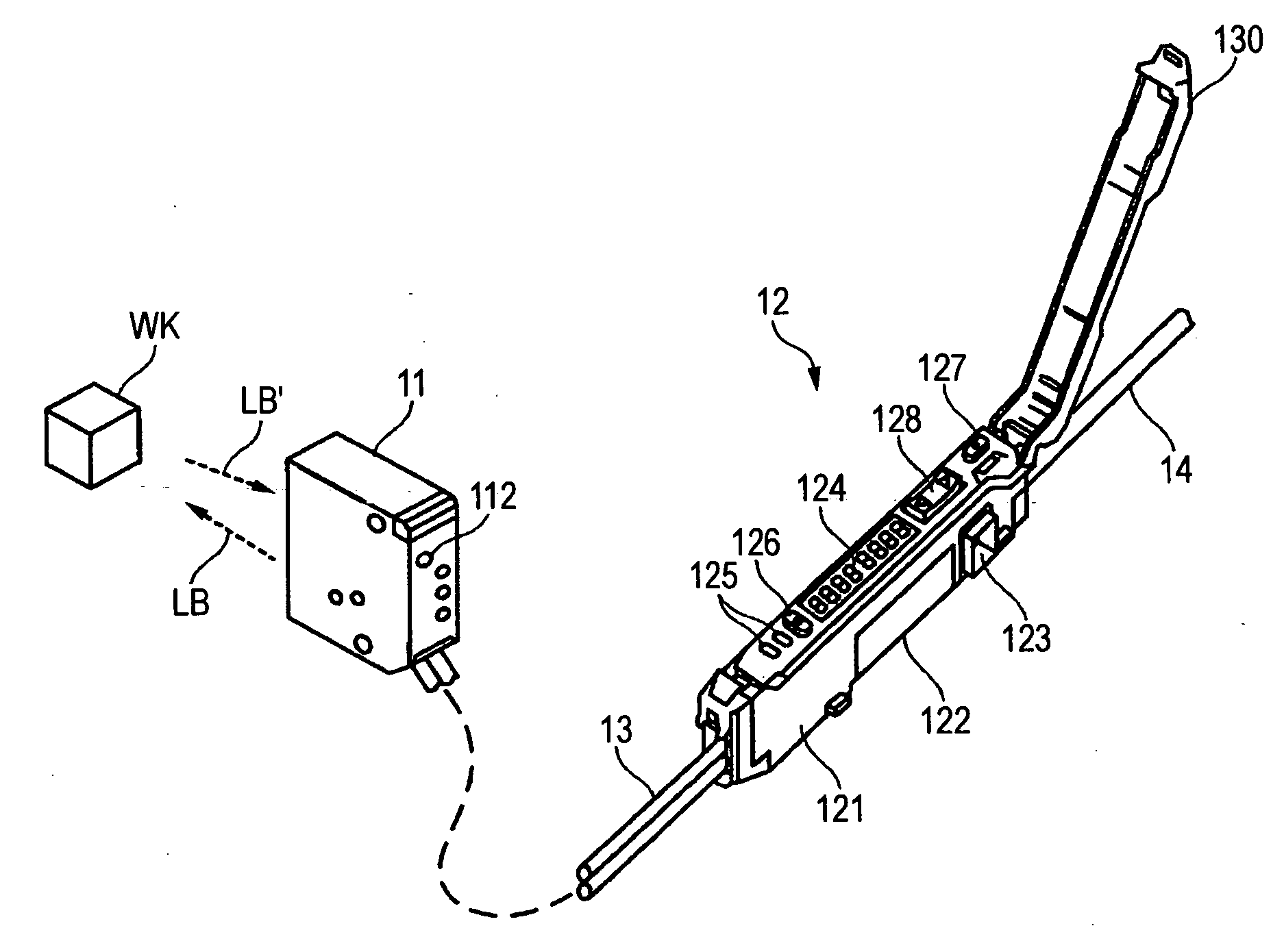
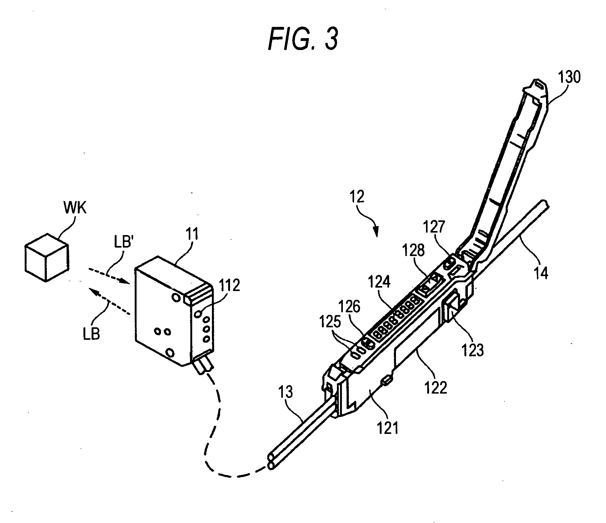
[0032]FIG. 3 is a perspective view showing an external appearance of a position sensitive photoelectric sensor according to an exemplary, non-limiting embodiment of the present invention. The position sensitive photoelectric sensor of this embodiment shows a so-called amplifier-separated type, and a head portion 11 and an amplifier portion 12 are connected via electric cables 13.

[0033] The amplifier portion 12 has a thin rectangular-parallelepiped case 121. The electric cables 13 connected to the head portion 11 are connected to the front end side of the case, and an electric cable 14 connected to an upper control equipment (PLC, or the like) is connected to the rear end side of the case. A structure fitted to the DIN rail (equipment fitting standard rail) is provided to a lower surface 122 of the case 121. A plurality of amplifier portions 12 can be fitted to the DIN rail and ...


PUM


Abstract

In a position sensitive photoelectric sensor that calculates a distance to a target based on a triangular range finding using a light and outputs a result compared with a reference distance, first the reference distance Dref is set roughly by using a light receiving portion adjusting mechanism that changes an angle of a light receiving portion including a reception lens and a light receiving device. Then, the change adjustment of the reference distance is performed by teaching. In addition, the user performs a fine adjustment of the reference distance by a manual adjustment using an increase / decrease key if necessary.

Description

[0001] The present application claims foreign priority based on Japanese Patent Application No. 2005-041435, filed Feb. 18, 2005, the content of which is incorporated herein by reference. BACKGROUND OF THE INVENTION [0002] 1. Technical Field [0003] The present invention relates to a position sensitive photoelectric sensor for sensing a distance to a target by a triangular range finding using a light, and a method of changing a reference distance set in the same. [0004] 2. Related Art [0005] This type photoelectric sensor is called a position sensor or a displacement sensor in some cases, and used to measure a distance to a target (referred to as a “work” hereinafter) based on a triangular range finding using a light. As shown in FIG. 1, a light emitting device 102 and a light receiving device 103 are arrange at a predetermined interval in a sensor head 101. A light projected from the light emitting device 102 is passed through a projection lens 104 and then projected onto a work WK....

Claims


Application Information

Patent Timeline
Patent Type & Authority Applications(United States)
IPC IPC(8): G01C3/08G01B11/14
CPCG01B11/026G01C3/08G01S7/497G01S17/48
Inventor SUGIYAMA, KAZUTOSHIOUE, TAKESHI
Owner KEYENCE
Why Eureka
Try Eureka