
LED pool or spa light having unitary lens body

Inactive Publication Date: 2006-08-24
DOYLE KEVIN
View PDF7 Cites 82 Cited by
  • Summary
  • Abstract
  • Description
  • Claims
  • Application Information

AI Technical Summary

Benefits of technology

[0015] A further object of the invention is to provide a light fixture with the ability to maximize the intensity and transmission of the light from an LED into a spa or pool and provide cooling of the LEDs, allowing them to be run at a higher intensity, through direct contact of the LEDs lens within the fixture to the water.
[0016] Yet another object of the invention is to provide an LED bulb with superior luminescence and coloring while maintaining durability, increasing dependability, increasing ease of maintenance, and decreasing manufacturing costs.
[0017] An object of the invention is to provide higher intensity LEDs without diminishing their operational life through the additional cooling provided by direct contact of the LEDs with the lens body that is in direct contact with the water in the pool or spa.
[0018] An object of the instant invention is to provide illumination of spa or pool by using light emitting diodes which are encapsulated or embedded inside a lens body with the LEDs exposed directly to the water or indirectly to the water through the enveloping of the LEDs in the lens body and the lens body directly contacting the water, using the water as a means of cooling the LEDs and preventing them from overheating and shortening the life of the LEDs.
[0019] A still further object of the instant invention is to provide a system for exposing LEDs without any gap of air or similar water tight space directly to the water in a pool or spa to provide better light transfer into the water, which yields better illumination of the pool or spa and the ability to wash several colors through the pool or spa.

Problems solved by technology

However, these incandescent bulb systems have a number of disadvantages.
Two of the principal disadvantages are a lack of reliability and durability.
An incandescent bulb system frequently fails during its initial warranty period.
The bulb filament is also very fragile, making transport and installation problematic.
This is true even after installation as the high temperatures needed during operation continue to make the filament susceptible to damage from swimmers impacts with the device.
This means that the system is difficult to maintain and even when properly maintained it can be easily damaged during normal operation.
These disadvantages are coupled with the fact that incandescent bulbs are inefficient and convert most of their energy to heat with as little as 10% of their energy producing light.
This inefficiency is further compounded by the fact that in heretofore known designs the light must be transmitted across a gap in the bulb and / or housing and then through a lens prior to reaching the transmission horizon with the water of the spa or pool resulting in further losses.
Thus, the typical incandescent system is unreliable, fragile, and inefficient at transmitting luminosity into the spa or pool.
Though these systems provide for waterproof LEDs, the lighting board and controllers are not encased in a singular housing encasing all the components necessary for pool or spa lights.
However, this system is ill suited for use in pools.
Though the LEDs are waterproofed by an encapsulation layer, the transmission through the oil to the lens provides only a limited increase in the transmission of luminosity of the LEDs.
The system fails to show an LED pool or spa lamp with a lens body with the LEDs encapsulated within the lens body.
This process does not provide for the type of housing utilized in the creation of a spa or pool light, as the shape and diffuser elements cannot be attained.
However, the air space diminishes the full transmission of the luminosity of the LED board and does not provide for additional cooling.
It also increases the production costs of the LED pool light disclosed, requiring additional manufacturing to provide the compartment.
However, the system still maintains a watertight air gap that decreases the transmission of light into the pool or spa and does not provide for sufficient heating of the LED elements.
This reduces the efficiency of the transmission of light from the LEDs to the pool or spa.
It does not allow for the more efficient cooling that is achieved by omitting the watertight compartment nor does it provide the improved cooling and reduced cost associated with omitting these gaps.
None of the aforementioned devices provides the ability to maximize the intensity and transmission of the light from the LED into the spa or pool and provide cooling of the LEDs, allowing them to be run at a higher intensity, through direct contact of the LEDs with a lens body within the fixture to the water.
Additionally, no feature has been able to achieve the desired superior luminescence, efficiency, and coloring while maintaining durability, increasing dependability, increasing ease of maintenance, and decreasing manufacturing costs.

Method used


Image

  • LED pool or spa light having unitary lens body
  • LED pool or spa light having unitary lens body
  • LED pool or spa light having unitary lens body

Examples


Embodiment Construction

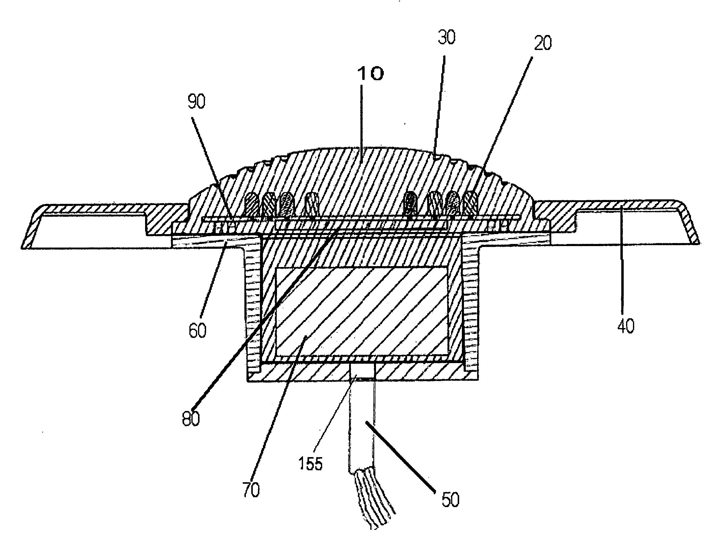
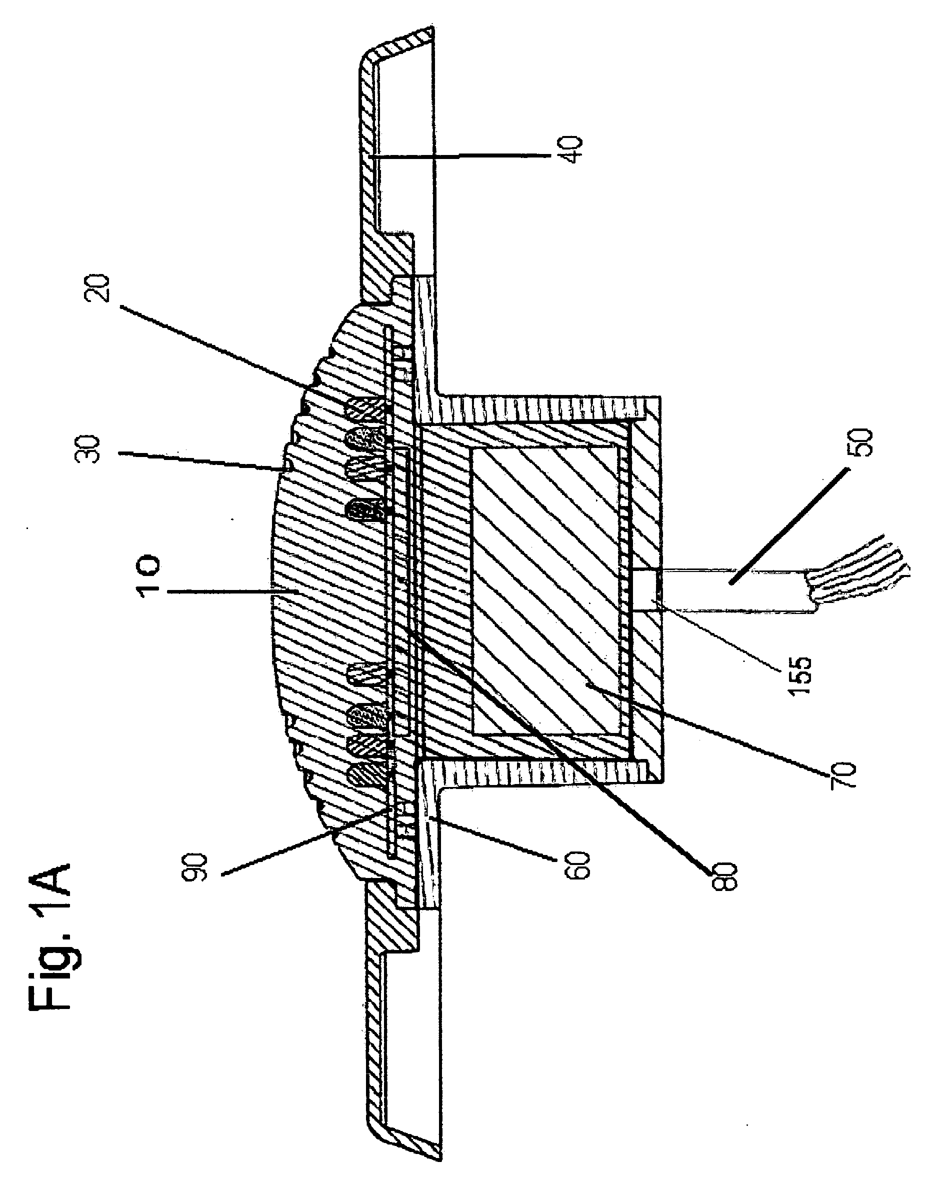
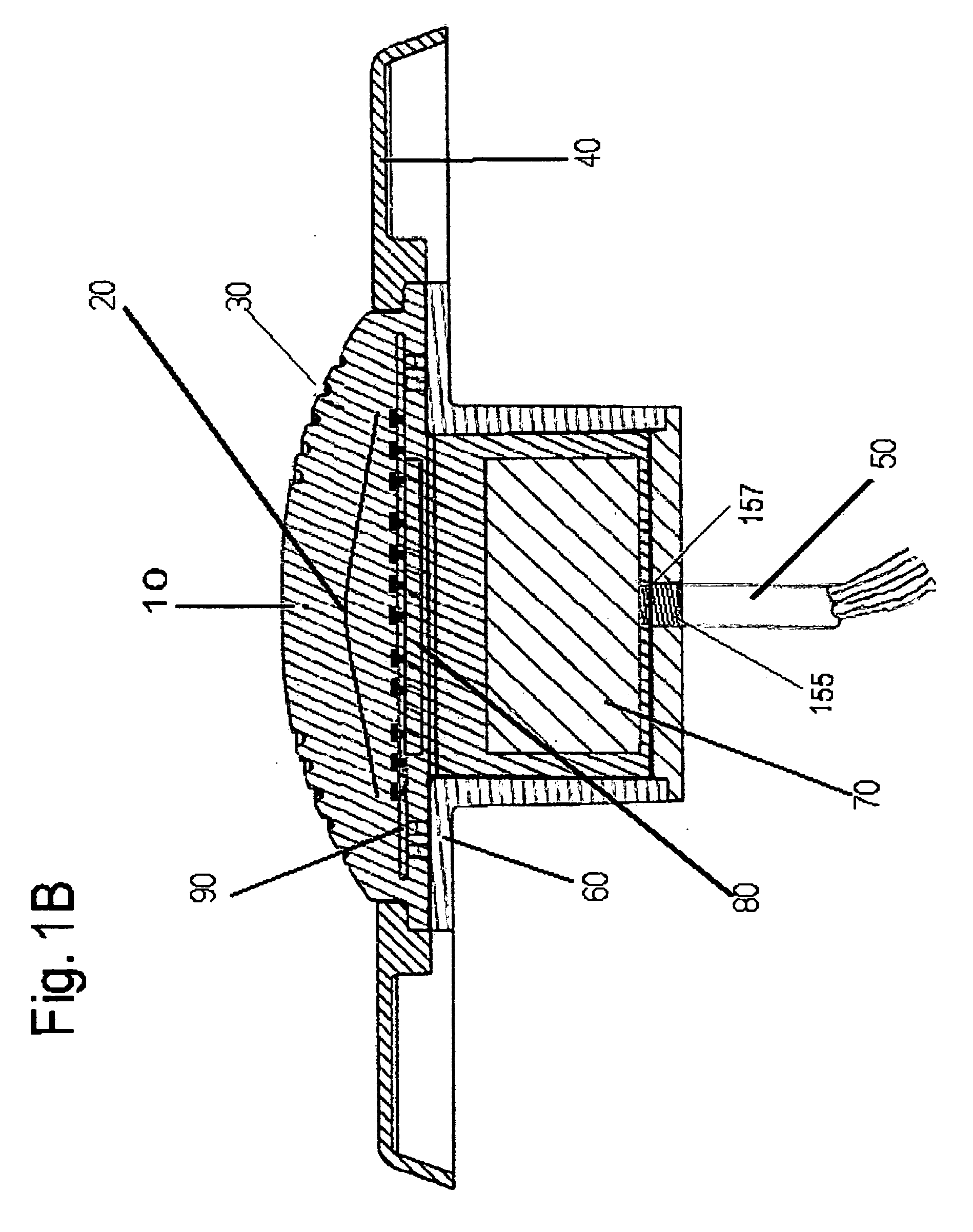
[0047] The instant invention is directed to a pool or spa light having an at least one LED or plurality of LEDs or a plurality of LEDs in an array with at least a portion of the LED, LEDs, or LED array 20 in direct contact with or encapsulated in a lens body 10. The at least one LED or plurality of LEDs 20 is encapsulated in an optically clear lens body 10 allowing light to pass through the lens body 10, the lens body 10 being in direct contact with the water of the pool or spa. The at least one LED 20 can be coupled to a controller 80 and a power source (not shown).

[0048]FIG. 1A illustrates a cross-sectional view of an exemplary embodiment of the instant invention. In the embodiment, a lens body 10 is shown with an at least one LED, in this case an LED array 20. The pool or spa light is set in a cavity 60 typically within the body of water being illuminated. The lens body 10 can be molded into a variety of shapes and sizes depending on the application. Some of these shapes will di...


PUM


Abstract

The instant invention is directed to a light emitting diode pool or spa lamp bulb having at least one light emitting diode with at least one lens body that is optically clear. The at least one light emitting diode being embedded in the lens body, the lens body being in direct contact with the pool or spa.

Description

CROSS REFERENCE TO RELATED APPLICATIONS [0001] This application claims benefit of the earlier filed U.S. Provisional Application No. 60 / 654,463 filed Feb. 22, 2005, which is incorporated herein by reference.FIELD OF THE INVENTION [0002] The invention relates to an apparatus and method for lighting water in a water feature, particularly for lighting water with Light Emitting Diodes (LEDs) in a pool or spa light, and even more particularly to an improved, unitary lens body pool or spa light having LEDs. BACKGROUND OF THE INVENTION [0003] Increasingly, the popularity of using water as an integral part of domestic landscaping has moved landscapers to push further and further into decorative aspects for these water features. These features are incorporated through swimming pools, spas, ponds, lakes and other water features and sources in the typical yard. In addition to the natural beauty associated with these features by applying the proper lighting the beauty of these water features ca...

Claims


Application Information

Patent Timeline
IPC IPC(8): F21V33/00
CPCF21S8/00F21S8/02F21V9/10F21V23/02F21V23/04F21V29/004F21V31/04F21W2131/401F21Y2101/02F21Y2113/005F21S2/00Y10S362/80F21Y2115/10F21Y2113/13F21V9/40F21V29/56F21S8/022
Inventor DOYLE, KEVIN
Owner DOYLE KEVIN
Learn More