

Electronic apparatus
a technology of electronic equipment and touch panel, which is applied in the direction of repeater circuits, instruments, and tactile signalling systems, etc., can solve the problems of small vibrating amplitude of conventional equipment and unsteady support of conventional equipmen
- Summary
- Abstract
- Description
- Claims
- Application Information
AI Technical Summary
Benefits of technology
Problems solved by technology
Method used
Image

Examples
first embodiment
[0031] Referring to FIGS. 1 to 3, a description will be directed to an electronic apparatus according to this invention.
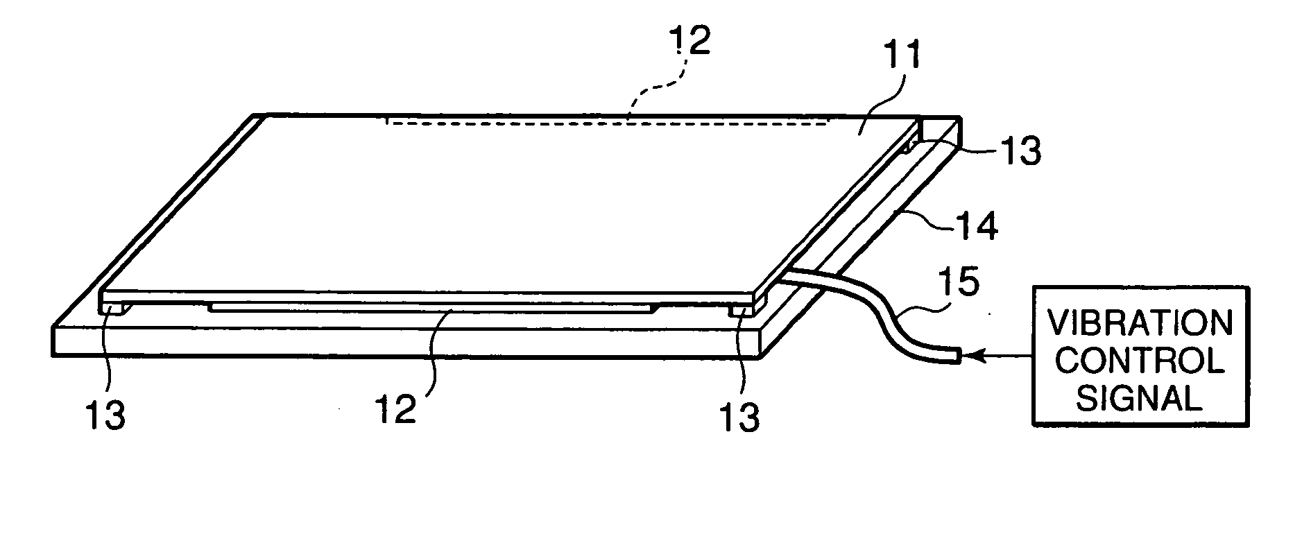
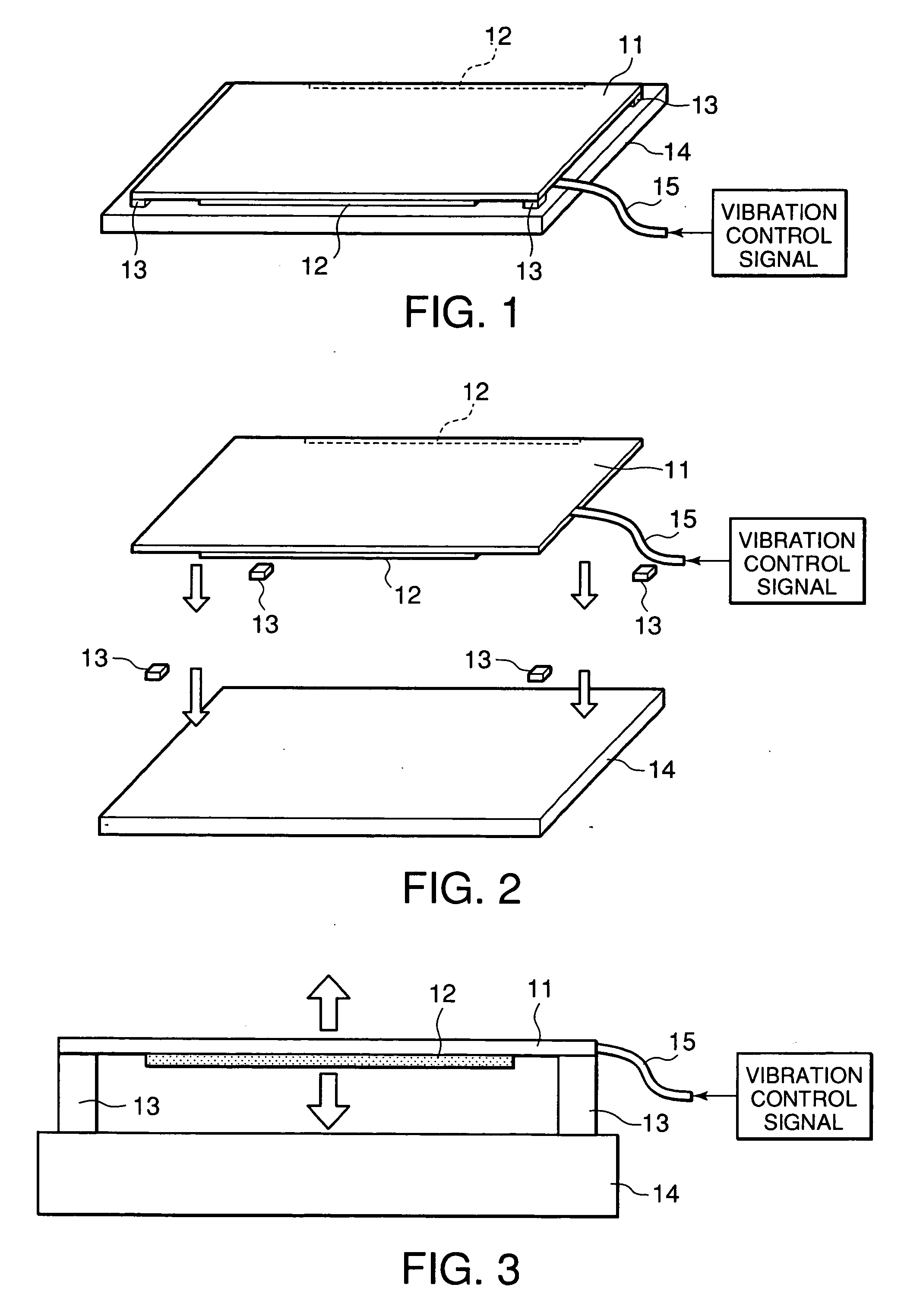
[0032]FIG. 1 is a perspective view of the electronic apparatus (or a panel assembly) of the first embodiment while FIG. 2 is an exploded perspective view thereof.
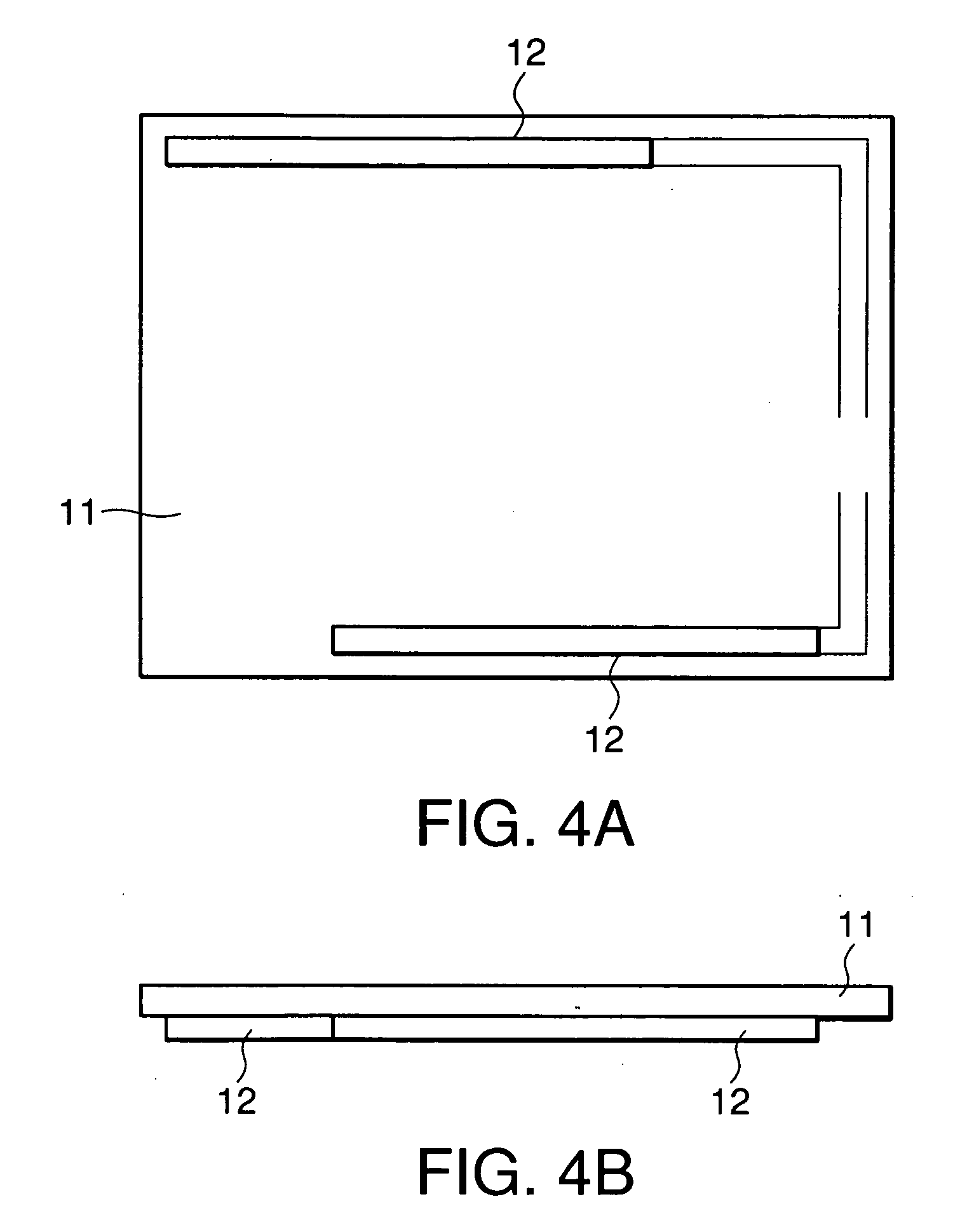
[0033] The electronic apparatus includes a rectangular touch panel (or a flat vibrating body) 11 having a glass or resinous substrate at a rear side thereof. On a rear surface of the touch panel 11, pair of vibrating elements 12 are fixed along upper (or rear side of FIG. 2) and lower (or front side of FIG. 2) edges of the touch panel 11. The rear surface of the touch panel 11 corresponds to an exposed surface of the glass or resinous substrate. Further, on the rear surface of the touch panel 11, four fixing cushions 13 are fixed at (vicinities of) four corners of the touch panel 11. A fixing frame 14 has a frame or rectangular shape, which is nearly equal to or slightly larger than the touch panel 11 in ...
second embodiment
[0041] Next, referring to FIGS. 5 to 7, the description will be made about an electronic apparatus (i.e. a POS terminal) according to this invention.
[0042] The electronic apparatus of FIG. 5 has a display and touch panel portion 51. The display and touch panel portion 51 includes a touch panel 52 with a vibrating function. FIG. 6 is an exploded perspective view of the display and touch panel portion 51. FIG. 7 is a partly sectional view of the display and touch panel portion 51.
[0043] The display and touch panel portion 51 serves as a display unit for displaying information and as an input unit for receiving input data. The display and touch panel portion 51 includes a front bezel 61, vibrating elements 62, fixing cushions 63, pressing cushions 64, a liquid crystal display panel (LCD) 65, and a rear cover 66, in addition to the touch panel 52. A combination of the touch panel 52, the vibrating elements 62, the fixing cushions 63, and the LCD 65 corresponds to the panel assembly of ...
third embodiment
[0051] Next, the description will be made about still another electronic apparatus (e.g. a panel assembly) according to this invention with reference to FIG. 8.
[0052] The electronic apparatus of this embodiment is similar to that of the first embodiment except for providing dustproof cushions 81.
[0053] As shown in FIG. 8, the providing dustproof cushions 81 disposed between the touch panel 11 and the fixing frame (e.g. LCD) 14 to from a rectangle having vertexes corresponding to the fixing cushions 13. In other words, each of the providing dustproof cushions 81 connects adjacent two of the fixing cushions 13. The dustproof cushions 81 are fixed to the touch panel 11 and the fixing frame 14 by double faced adhesive tapes, adhesive material, or the like, similarly as for the fixing cushions 13. The dustproof cushions 81, as understood from the name, prevent dust from coming in the space between the touch panel 11 and the fixing frame 14. The dustproof cushions 81 are made of material...
PUM
 Abstract
Description
Claims
Application Information