Image forming device, image forming method, and computer readable recording medium stored with image forming program
- Summary
- Abstract
- Description
- Claims
- Application Information
AI Technical Summary
Benefits of technology
Problems solved by technology
Method used
Image
Examples
Example
[0037] Next, the operation of the printer 1 according to the first embodiment will be described in the following.
[0038]FIG. 3 is a flowchart showing the sequence of process on the printer 1 according to the first embodiment of the present invention. The algorithm shown in the flow chart of FIG. 3 is stored as a program in the storage unit 12 of the printer 1 and executed by the control unit 11.
[0039] First, referring to FIG. 3, the printer 1 waits until the printing job is received (S101: No).
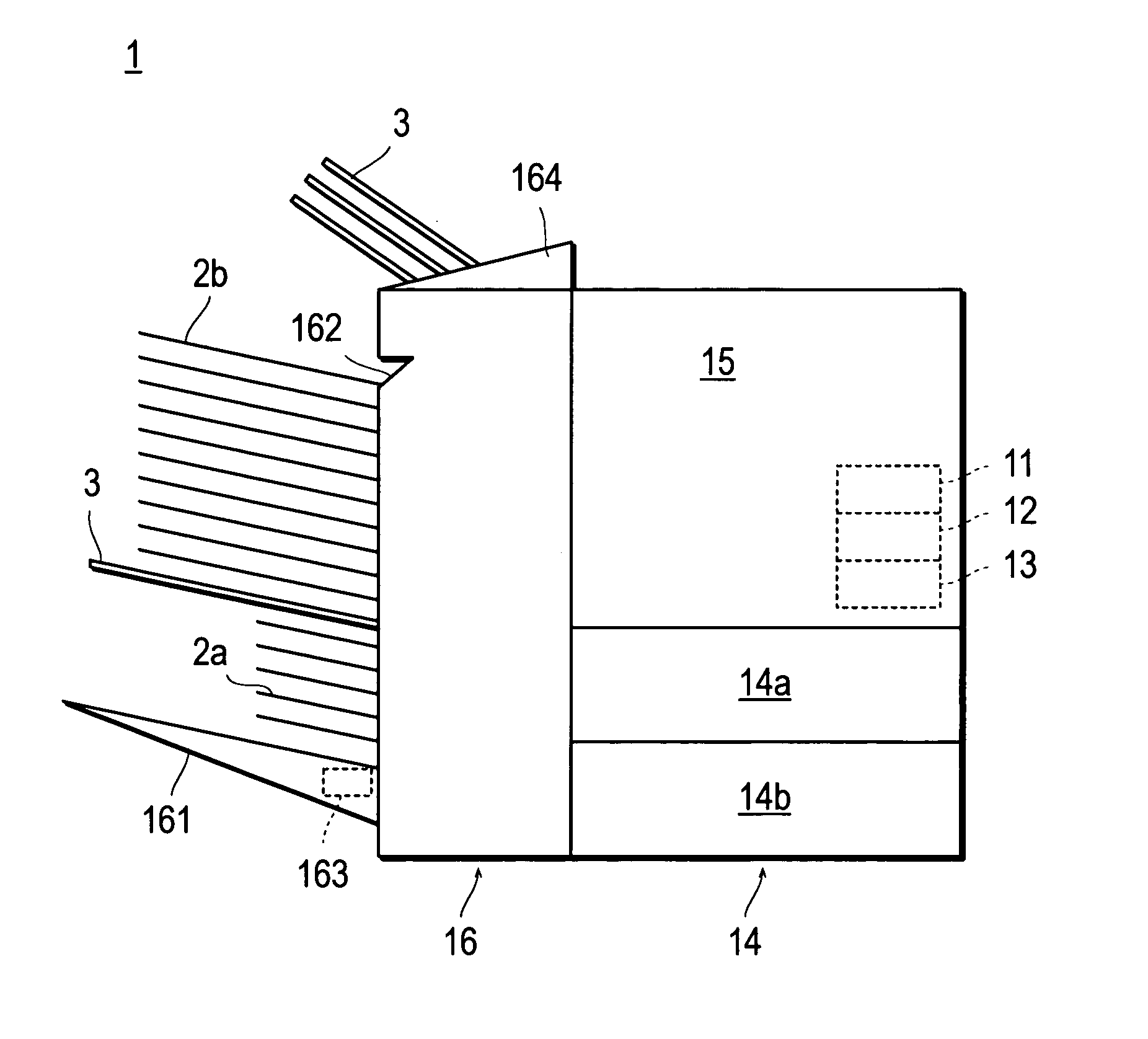
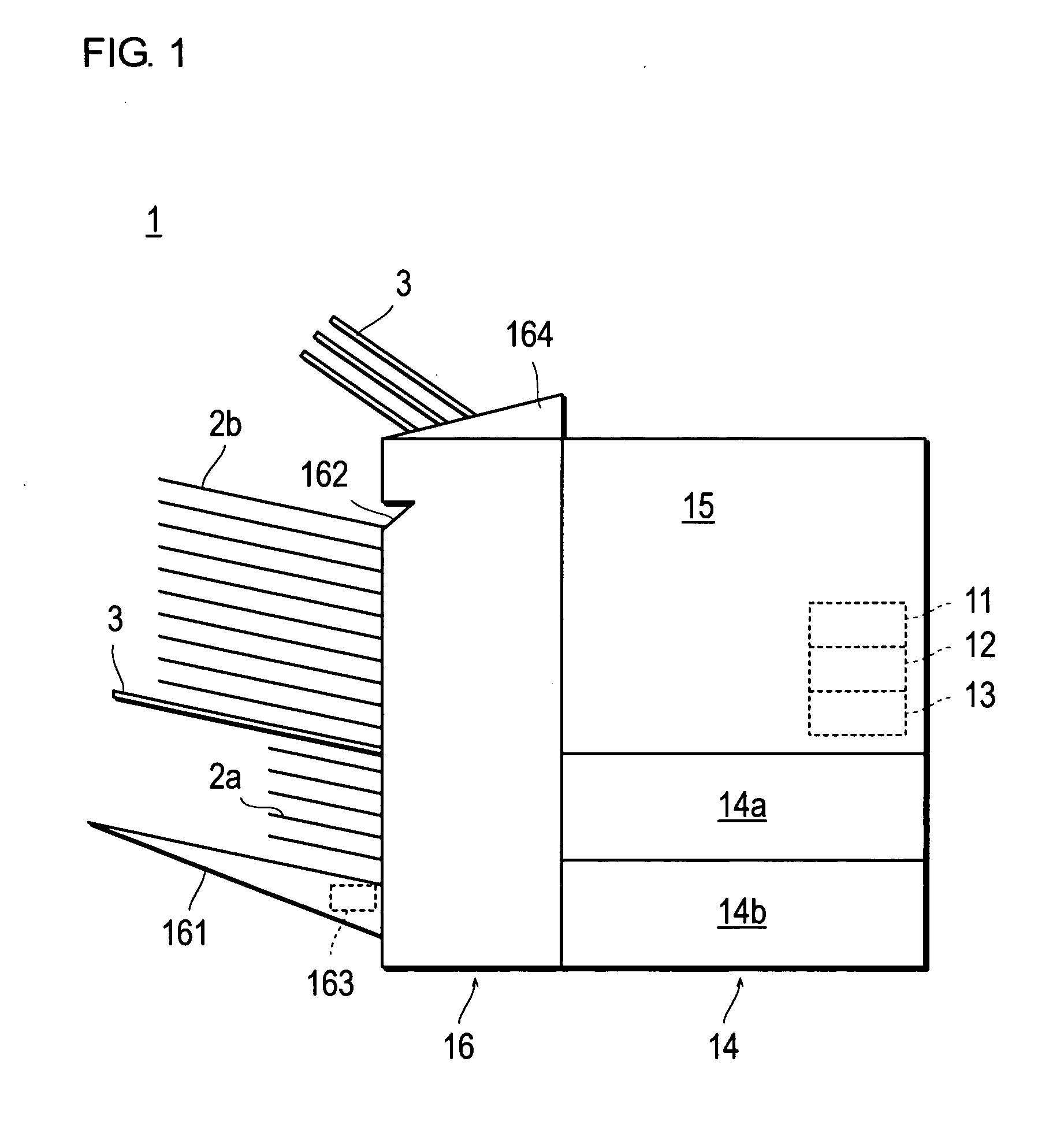
[0040] When a printing job is received via the interface unit 13 (S101: Yes), a judgment will be made as to whether any paper is left on the paper tray 161 based on the detection signal of the paper detection unit 163 (S102).
[0041] If it is judged that no paper exists on the paper tray 161 (S102: No), the operation advances to the step S105.
[0042] In the step S105, the image forming process is performed. More specifically, the control unit 11 transmits the paper supply signal to the paper ...
Example
[0051] Next, the second embodiment of the invention will be described below. The second embodiment is different from the first embodiment in that the number of supporting members 3 to be supplied varies with the volume of paper that can be further loaded on the paper tray 161. The following description will concentrate mainly on those points that are different from the first embodiment.
[0052]FIG. 5 and FIG. 6 are flowcharts showing the sequence of process on the printer 1 according to a second embodiment of the present invention. The algorithm shown in the flow charts of FIG. 5 and FIG. 6 is stored as a program in the storage unit 12 of the printer 1 and executed by the control unit 11.
[0053] The steps S201 through S203, S205, and S206 shown in FIG. 5 are identical to the steps S101 through S103, S105, and S106 shown in FIG. 3, so that their descriptions are not repeated here.
[0054] The discharging process of the supporting member 3 in the step S204 will be described below with r...
Example
[0061] Next, the third embodiment of the invention will be described below. The third embodiment is different from the second embodiment in that a portion of the multiple pieces of supporting member determined in accordance with the amount of loadable paper is discharged every time a certain number of sheets of paper is discharged on said sheets of paper. The following description will concentrate mainly on those points that are different from the second embodiment.
[0062]FIG. 7 is a flowchart showing the sequence of process on the printer 1 according to a third embodiment of the present invention. The algorithm shown in the flow chart of FIG. 7 is stored as a program in the storage unit 12 of the printer 1 and executed by the control unit 11.
[0063] The steps S401 through S403, S406, and S407 shown in FIG. 7 are identical to the steps S201 through S203, S205, and S206 shown in FIG. 5, so that their descriptions are not repeated here.
[0064] First, the process for deciding the numbe...
PUM
 Abstract
Description
Claims
Application Information
 - R&D Engineer
- R&D Manager
- IP Professional
- Industry Leading Data Capabilities
- Powerful AI technology
- Patent DNA Extraction
Browse by: Latest US Patents, China's latest patents, Technical Efficacy Thesaurus, Application Domain, Technology Topic.
© 2024 PatSnap. All rights reserved.Legal|Privacy policy|Modern Slavery Act Transparency Statement|Sitemap


