Liquid ejecting head and liquid ejecting apparatus

Active Publication Date: 2020-06-25
SEIKO EPSON CORP
View PDF0 Cites 1 Cited by
  • Summary
  • Abstract
  • Description
  • Claims
  • Application Information

AI Technical Summary

Benefits of technology

The present invention is about a liquid ejecting head and apparatus that prevents cross talk and improves rigidity. The invention prevents the flow path substrate from getting bigger and the partition wall between flow paths from getting weaker. This results in better performance and efficiency of the liquid ejecting system.

Problems solved by technology

In the ink jet type recording head described above, if air bubbles stay in the pressure chamber, the air bubbles absorb the pressure change induced by the energy generating element, and thus it is not possible to normally discharge the ink droplets from the nozzle.
In the ink jet type recording head described above, there is a demand for reducing a flow path resistance or an inertance without lowering the resolution of the nozzle, but if the cross-sectional area of the flow path is enlarged, there is a problem such as a size increase of a flow path substrate, a reduction in the rigidity of a partition wall between the flow paths, or the occurrence of cross talk.
The above-mentioned problem exists not only in the ink jet type recording head, similarly but also in liquid ejecting heads that eject liquids other than an ink.

Method used


Image

  • Liquid ejecting head and liquid ejecting apparatus
  • Liquid ejecting head and liquid ejecting apparatus
  • Liquid ejecting head and liquid ejecting apparatus

Examples


embodiment 1

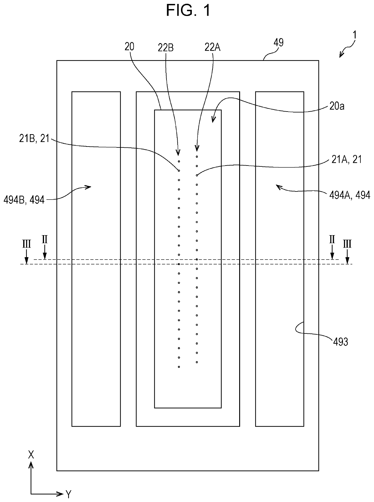
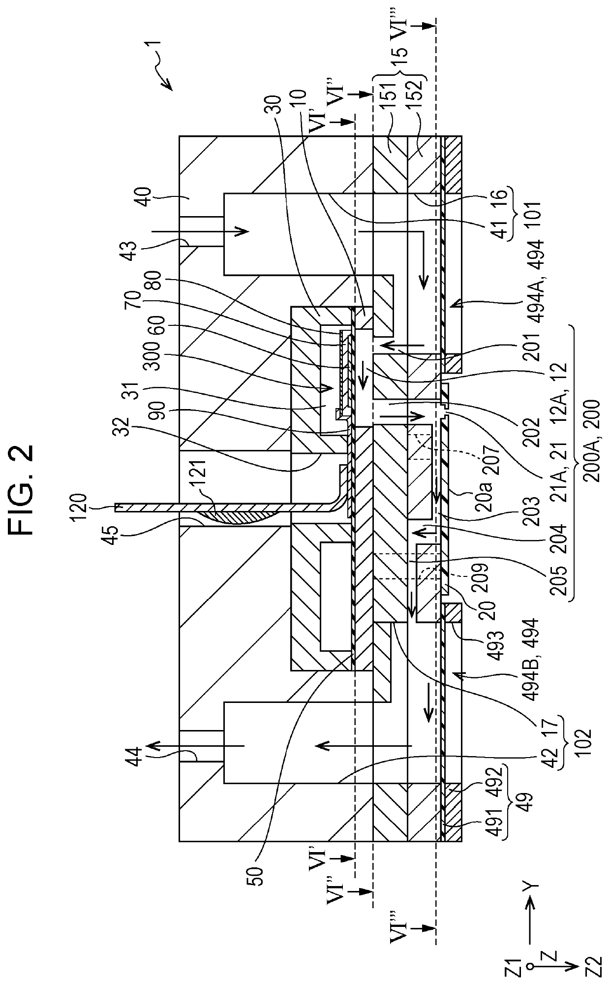
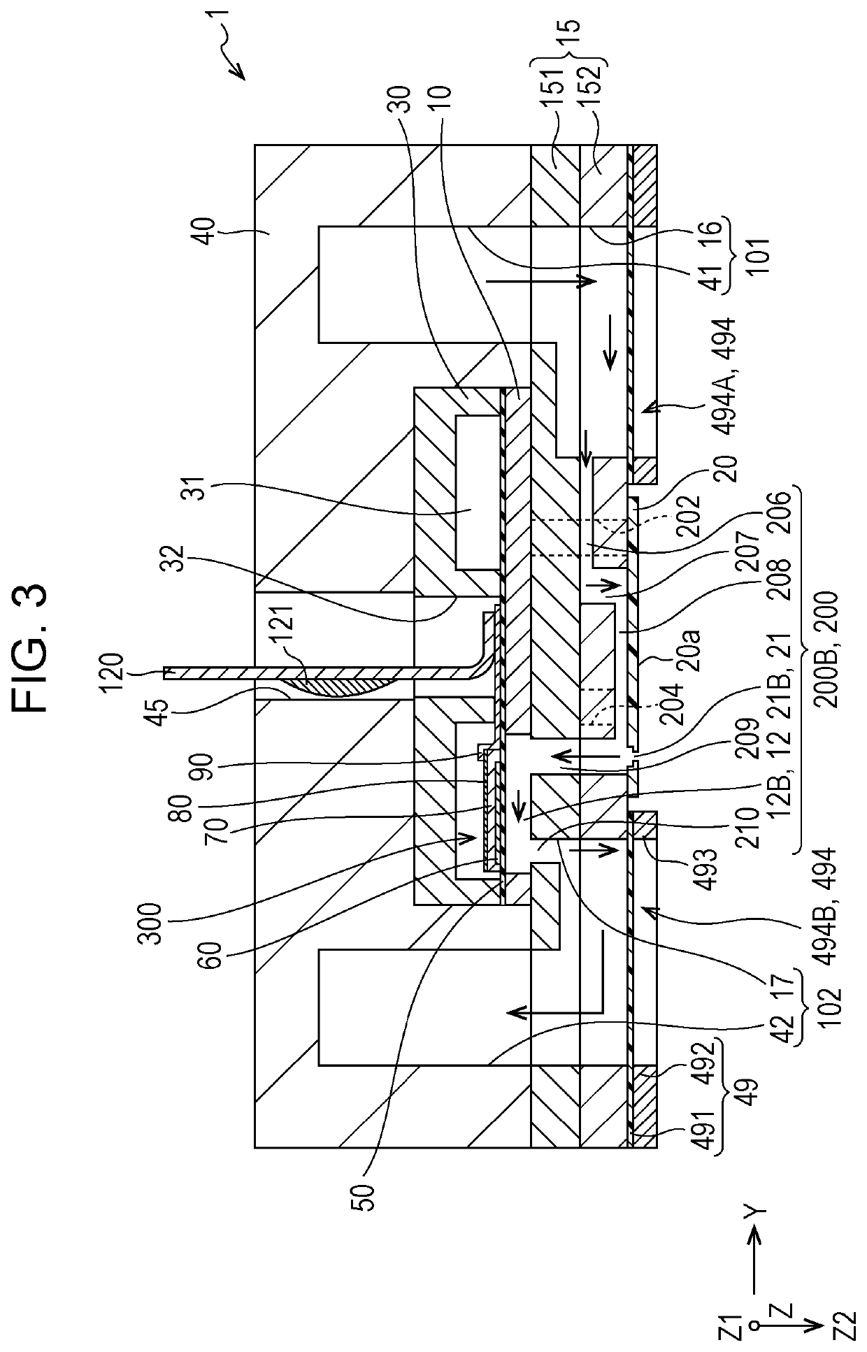
[0023]An ink jet type recording head of an embodiment which is one example of a liquid ejecting head will be described with reference to FIGS. 1 to 7. Incidentally, FIG. 1 is a plan view of the ink jet type recording head which is one example of a liquid ejecting head according to Embodiment 1 of the present disclosure, which is seen from a nozzle surface side. FIG. 2 is a cross-sectional view taken along a line II-II in FIG. 1. FIG. 3 is a cross-sectional view taken along a line III-III in FIG. 1. FIG. 4 is a diagram schematically illustrating flow paths. FIG. 5 is a perspective view of the flow paths seen from a Z2 side. FIG. 6 is a cross-sectional view of a main part of the recording head, a cross-sectional view taken along a line VI′-VI′ in FIG. 2, a cross-sectional view taken along a line VI″-VI″ in FIG. 2, and a cross-sectional view taken along a line VI′″-VI′″ in FIG. 2. FIG. 7 is a cross-sectional view taken along a line VII-VII in FIG. 6.

[0024]An ink jet type recording head...

embodiment 2

[0127]FIG. 8 is a perspective view seen from the Z2 side illustrating flow paths of an ink jet type recording head which is one example of a liquid ejecting head according to Embodiment 2 of the present disclosure. FIG. 9 is a cross-sectional view of a main part of the recording head of the embodiment taken along a line IX-IX in FIG. 6. Incidentally, the same reference signs are assigned to the same members as those in the embodiment described above, and the duplicated description will be omitted.

[0128]Similar to Embodiment 1 described above, the flow path formation substrate 10, the communication plate 15, the nozzle plate 20, the compliance substrate 49, and the case member 40 which are a flow path substrate having the first common liquid chamber 101, the second common liquid chamber 102, and a plurality of the individual flow paths 200.

[0129]In addition, the individual flow path 200 has the first individual flow path 200A and the second individual flow path 200B.

[0130]The first i...


PUM


Abstract

A liquid ejecting head includes first and second individual flow paths arranged side by side along a first direction; a first nozzle communicating with the first individual flow path; a second nozzle communicating with the second individual flow path; and a common liquid chamber coupled to the first and second individual flow paths. The first and second nozzles have openings in a nozzle surface having a second direction as a normal direction. The first individual flow path has a first upstream communication path extending between the first nozzle and the common liquid chamber along the second direction. The second individual flow path has a second upstream communication path extending between the second nozzle and the common liquid chamber along the second direction. The first upstream communication path and the second upstream communication path have parts which do not overlap each other when seen along the first direction.

Description

[0001]The present application is based on, and claims priority from JP Application Serial Number 2018-239220, filed Dec. 21, 2018, the disclosure of which is hereby incorporated by reference herein in its entirety.BACKGROUND1. Technical Field[0002]The present disclosure relates to a liquid ejecting head and a liquid ejecting apparatus which eject a liquid from a nozzle, particularly, to an ink jet type recording head and an ink jet type recording apparatus which discharge an ink as a liquid.2. Related Art[0003]As a liquid ejecting head that ejects a liquid, there is known an ink jet type recording head that performs printing by discharging an ink as a liquid onto a printed medium.[0004]The ink jet type recording head includes an individual flow path having a pressure chamber that communicates with a nozzle, a common liquid chamber that communicates in common with a plurality of the individual flow paths, and an energy generating element such as a piezoelectric actuator that induces ...

Claims


Application Information

Patent Timeline
IPC IPC(8): B41J2/14
CPCB41J2002/14338B41J2/14145B41J2/1404B41J2/01B41J2/14233B41J2202/12B41J2002/14241B41J2002/14491B41J2002/14419
Inventor FUKUZAWA, YUMAUCHIDA, KAZUAKIFUKUDA, SHUNYA
Owner SEIKO EPSON CORP
Why Eureka
Try Eureka