Gap detector, liquid ejecting apparatus incorporating the same, and gap detecting method executed in the apparatus

a liquid ejecting apparatus and gap detection technology, applied in the field of gap detection, can solve the problems of paper jamming, reducing the number of components, and becoming a factor for incurring a cost increase, and achieve the effect of low cos

Inactive Publication Date: 2006-08-31
SEIKO EPSON CORP
View PDF3 Cites 8 Cited by
  • Summary
  • Abstract
  • Description
  • Claims
  • Application Information

AI Technical Summary

Benefits of technology

[0012] It is therefore an object of the invention to provide a gap sensor capa...

Problems solved by technology

However, the above technique requires a plurality of exclusive sensors for detecting a plurality of platen gaps, which has become a factor for incurring a cost hike.
This technique also raises the following problem.
With this configuration, the number of components can be curtailed, which is preferable in terms of cost However, the construction raises the following problem.
Specifically, when a recording sheet is present in a position where a carriage opposes a recording head during the course of the carriage proceeding to press the actuated member, the recording head may rub against the recording sheet when switching to t...

Method used


Image

  • Gap detector, liquid ejecting apparatus incorporating the same, and gap detecting method executed in the apparatus
  • Gap detector, liquid ejecting apparatus incorporating the same, and gap detecting method executed in the apparatus
  • Gap detector, liquid ejecting apparatus incorporating the same, and gap detecting method executed in the apparatus

Examples


Embodiment Construction

[0079] Embodiments of the invention will be described below in detail with reference to the accompanying drawings.

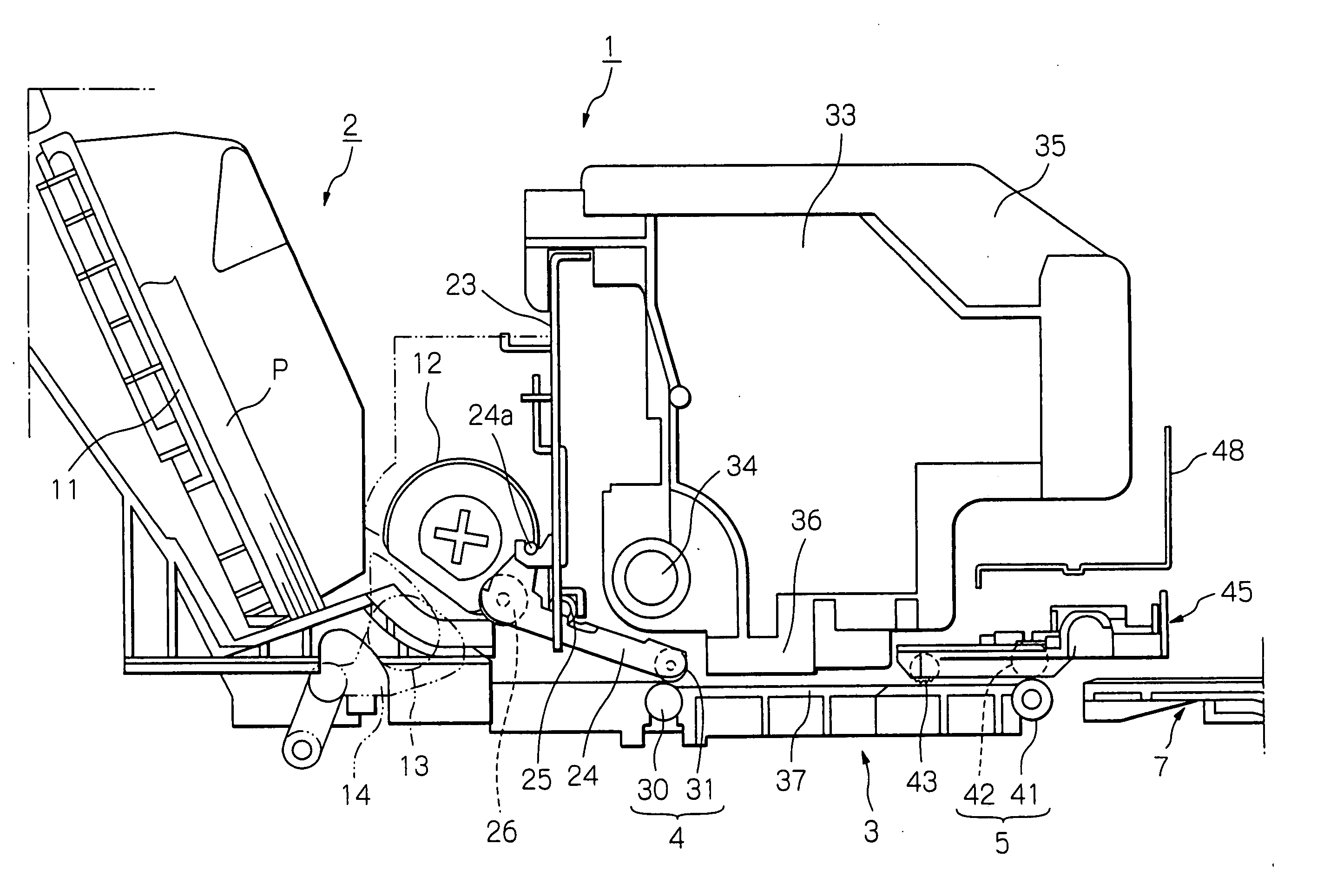
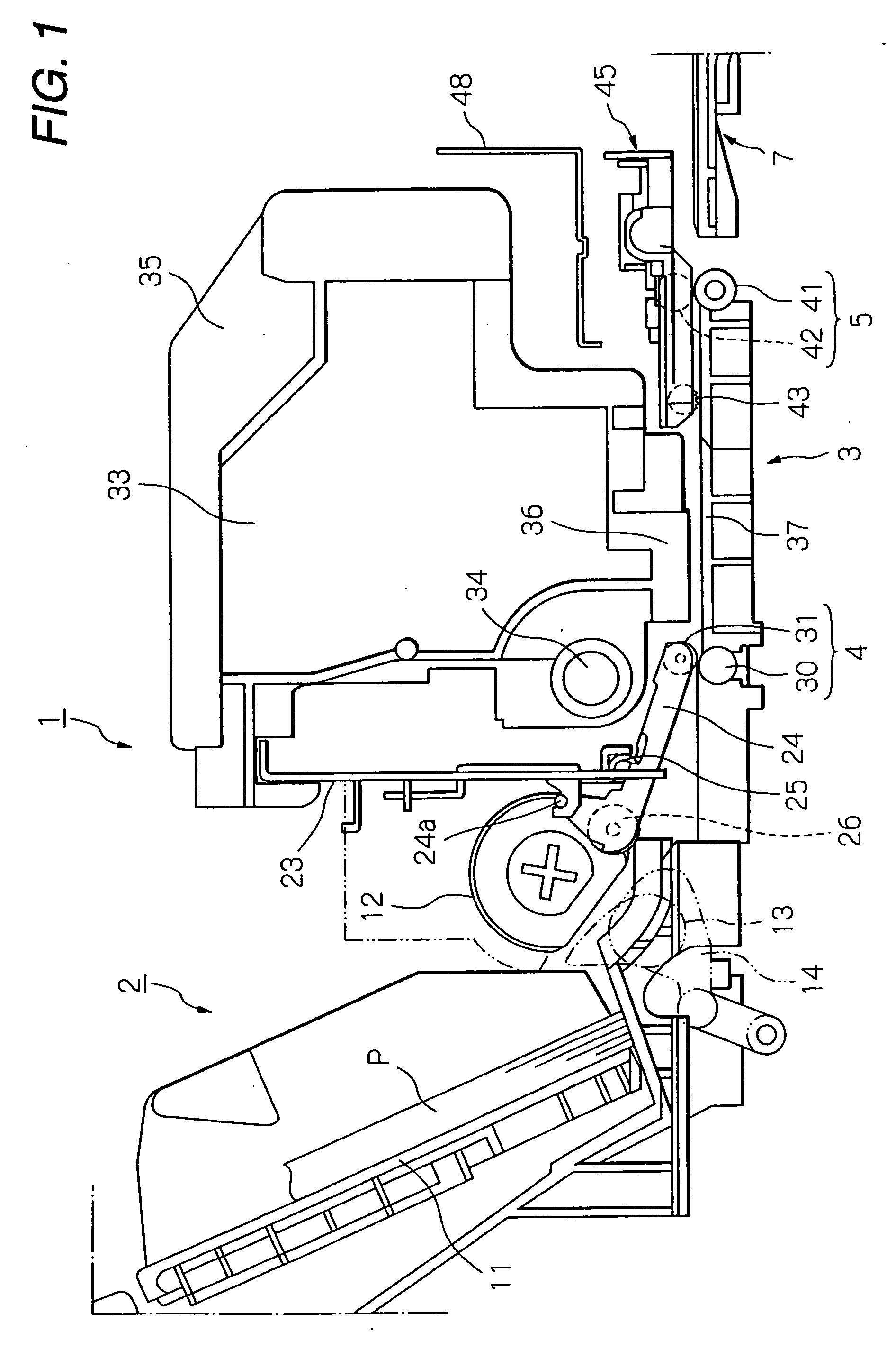
[0080] An ink jet printer (hereinafter simply called a “printer”) 1, which is employed as an example of a recording apparatus or a liquid ejecting apparatus, will be described as one embodiment. In the following description, the right direction (the front side of the printer) in FIG. 1 will be referred to as “downstream” relative to a transporting direction of a recording medium (target medium). The left direction (the rear side of the printer) will be referred to as “upstream” relative to the transporting direction.

[0081] A feeder 2, into which recording media (target media) P in a cut-sheet form (hereinbelow referred to as “sheet P”) can be set in an inclined posture, is provided in a rear section of the printer 1. A sheet P is fed from the feeder 2 to a transporter 4 located downstream. The thus-fed sheet P is transported downstream to a recording section 3 by the t...


PUM


Abstract

A gap detector is operable to detect a distance between a liquid electing head adapted to eject liquid toward a target medium and a platen adapted to support the target medium. A circular plate is adapted to be provided on a guide shaft which is rotated together with the rotary plate to selectively determine the distance as one of a plurality of distances. The circular plate has a plurality of flags formed on an outer periphery, each of which is associated with one of the distances. A sensor is disposed in the vicinity of the outer periphery of the circular plate and operable to output a signal indicative of a passage of each of the flags in accordance with the rotation of the circular plate. At least one of intervals between the flags in a circumferential direction of the circular plate is made different from the other.

Description

BACKGROUND OF THE INVENTION [0001] The present invention relates to a gap detector for detecting a gap between a liquid ejecting head and a target medium by detecting a rotating state of a carriage guide shaft. [0002] The present invention also relates to a liquid ejecting apparatus incorporating such a gap detector and to a gap detecting method executed in such a liquid ejecting apparatus. [0003] The liquid ejecting apparatus is not limited to a recording apparatus, such as a printer, a copier, or a facsimile, which employs an ink jet recording head and ejects ink from the recording head to a recording medium, to thus effect recording. The liquid ejecting apparatus is employed to encompasses an apparatus that ejects a liquid appropriate to an application, in place of ink from a liquid ejecting head corresponding to the ink jet recording head onto a target medium corresponding to a recording medium, thereby causing the liquid to adhere to the medium. [0004] In addition to the record...

Claims


Application Information

Patent Timeline
IPC IPC(8): B41J1/08
CPCB41J3/4071B41J25/308B41J25/3088
Inventor FUKUMASU, KEIICHIROHASHII, KAZUHIROFURUYAMA, MASAFUMI
Owner SEIKO EPSON CORP
Why Eureka
Try Eureka