Locking device and a vehicle seat

a technology for locking devices and vehicle seats, which is applied in the direction of furniture parts, machine supports, other domestic objects, etc., can solve the problems of increasing noise, and achieve the effects of reducing noise, reducing noise, and reducing nois

Active Publication Date: 2015-05-21
KEIPER SEATING MECHANISMS CO LTD
View PDF5 Cites 4 Cited by
  • Summary
  • Abstract
  • Description
  • Claims
  • Application Information

AI Technical Summary

Benefits of technology

[0013]According to a preferred embodiment of the present invention, it is provided that a first pivot movement of the catch from the locking position in the direction of the unlocking position is essentially aligned parallel to another first pivot movement of the compensation element from the contact position in the direction of the release position and a second pivot movement of the catch from the unlocking position in the direction of the locking position is essentially aligned parallel to another second pivot movement of the compensation element from the release position in the direction of the contact position. The pivot movements of the compensation element and the catch are essentially parallel such that the coupling mechanism can be implemented simply without the need for other moving parts. In addition, space for the catch and the compensation element is needed on just one side of the retainer region and so a more compact construction is achieved. The catch preferably comprises a first jaw which is open on one side for partially encompassing the counter element in the locking position, and the compensation element comprises a second jaw which is open on one side, for parti...

Problems solved by technology

The disadvantage of such locking devices is that the catch must be slightly spaced from the counter element to ensure that any manufacturing tolerances cannot adversely affect the locking of the counter element by means of the catch.
However, the short distance bet...

Method used


Image

  • Locking device and a vehicle seat
  • Locking device and a vehicle seat
  • Locking device and a vehicle seat

Examples


Embodiment Construction

[0022]In the different figures, the same parts are always provided with the same reference signs and are thus, as a rule, only named or mentioned once.

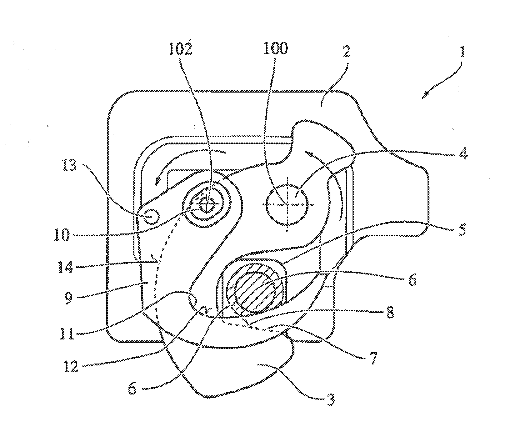
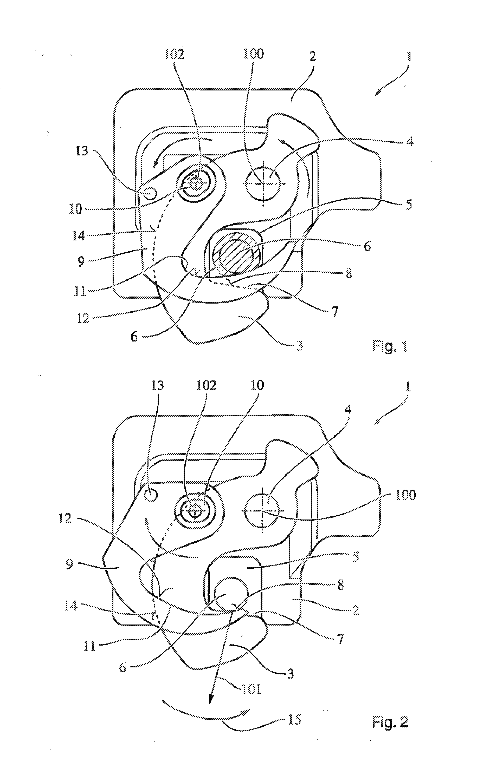
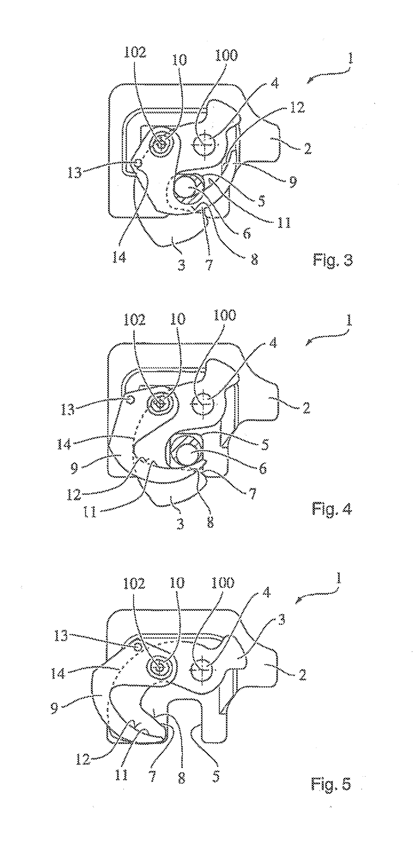
[0023]FIGS. 1 to 5 show a schematic view of the locking device (1) according to an exemplary embodiment of the present invention in different operating states.

[0024]The locking device (1) comprises a basic structure (2) in the form of a base plate or a housing, in which a swivel-mounted catch (3) is arranged via a first bearing journal (4). The basic structure (2) also comprises a retainer region (5) shaped like a jaw for receiving a counter element (6). The counter element (6) comprises, for example, a journal which has to be locked in the retainer region (5) by means of the locking device (1). It is conceivable that a vehicle seat or another component of a car is to be reversibly and releasably fixed to the body of the vehicle or in the interior of the vehicle by means of the locking device (1).

[0025]To achieve this, the catch (3) c...


PUM


Abstract

The invention related to a locking device (1), particularly for a vehicle sent, which comprises a retainer region (5) for receiving a counter element (6), a catch (3) which can be pivoted between a locking position that locks the counter element in said retainer region, and an unlocking position, and a compensation element (9) that can be pivoted between a contact position for tensioning the counter element in the direction of the retainer region and a release position for releasing said counter element.

Description

PRIOR ART[0001]The present invention relates to a locking device, particularly for a vehicle seat, which comprises a retainer region for receiving a counter element, a catch which can be pivoted between a locking position that locks the counter element in said retainer region, and an unlocking position.[0002]Such locking devices are generally known. For example, from the publication DE 10 2004 001 766 B3 a locking device for a vehicle seat is known which consists of a housing comprising a ground plane, a swivel-mounted catch arranged in the housing which can be pivoted for locking with a counter element and at least one swivel-mounted retaining element, also mounted in the housing, which, through interaction with the catch, assures a locked state.[0003]The disadvantage of such locking devices is that the catch must be slightly spaced from the counter element to ensure that any manufacturing tolerances cannot adversely affect the locking of the counter element by means of the catch. ...

Claims


Application Information

Patent Timeline
IPC IPC(8): B60N2/015B60N2/90
CPCB60N2/01583B60N2/366B60N2205/20B60N2/015B60N2/01508B60N2/01516B60N2/01541
Inventor GORDEENKO, IGOR
Owner KEIPER SEATING MECHANISMS CO LTD
Why Eureka
Try Eureka