
Multiple heavy bag stand

Inactive Publication Date: 2006-08-31
VALENTINE ROBERT R
View PDF4 Cites 13 Cited by
  • Summary
  • Abstract
  • Description
  • Claims
  • Application Information

AI Technical Summary

Benefits of technology

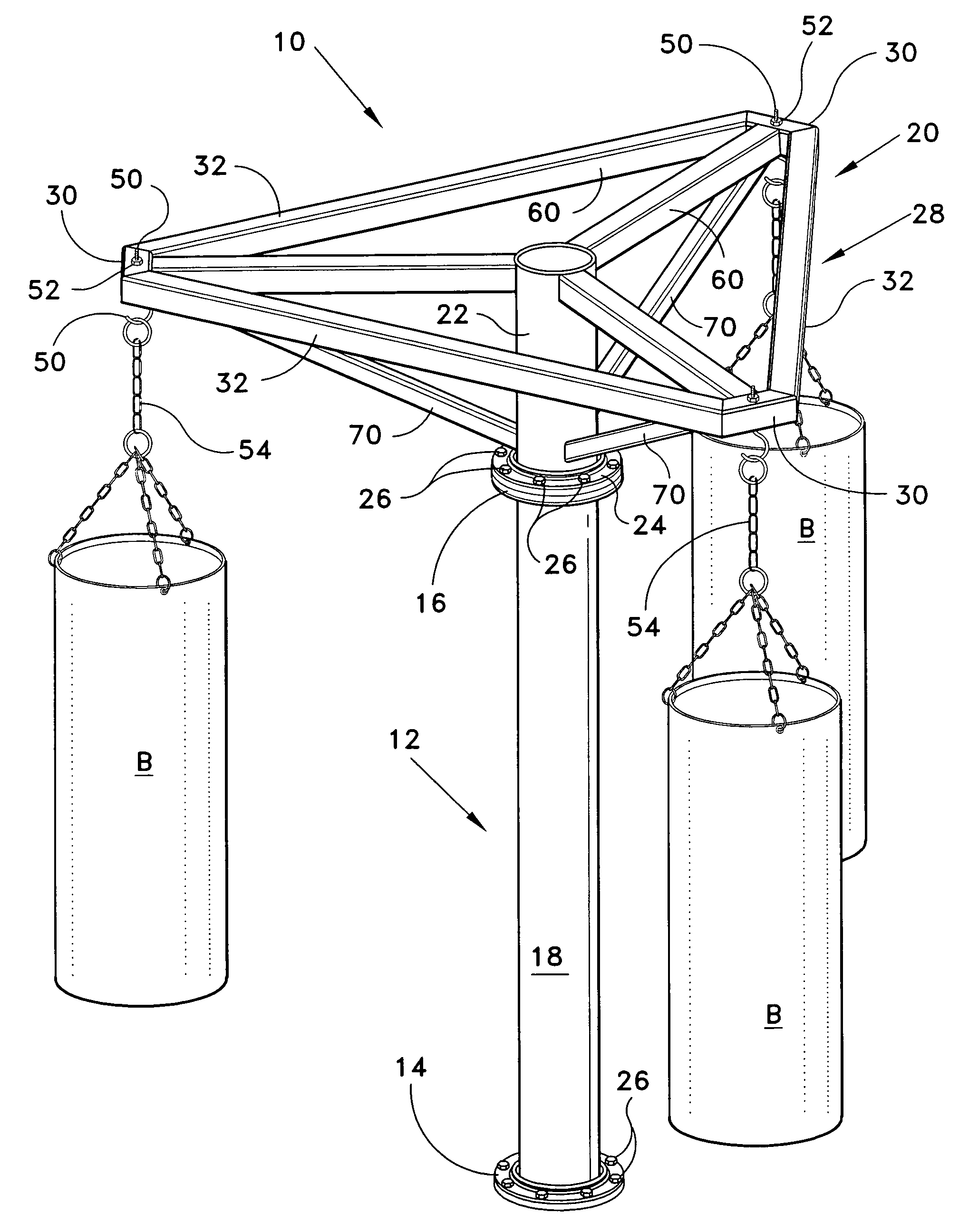
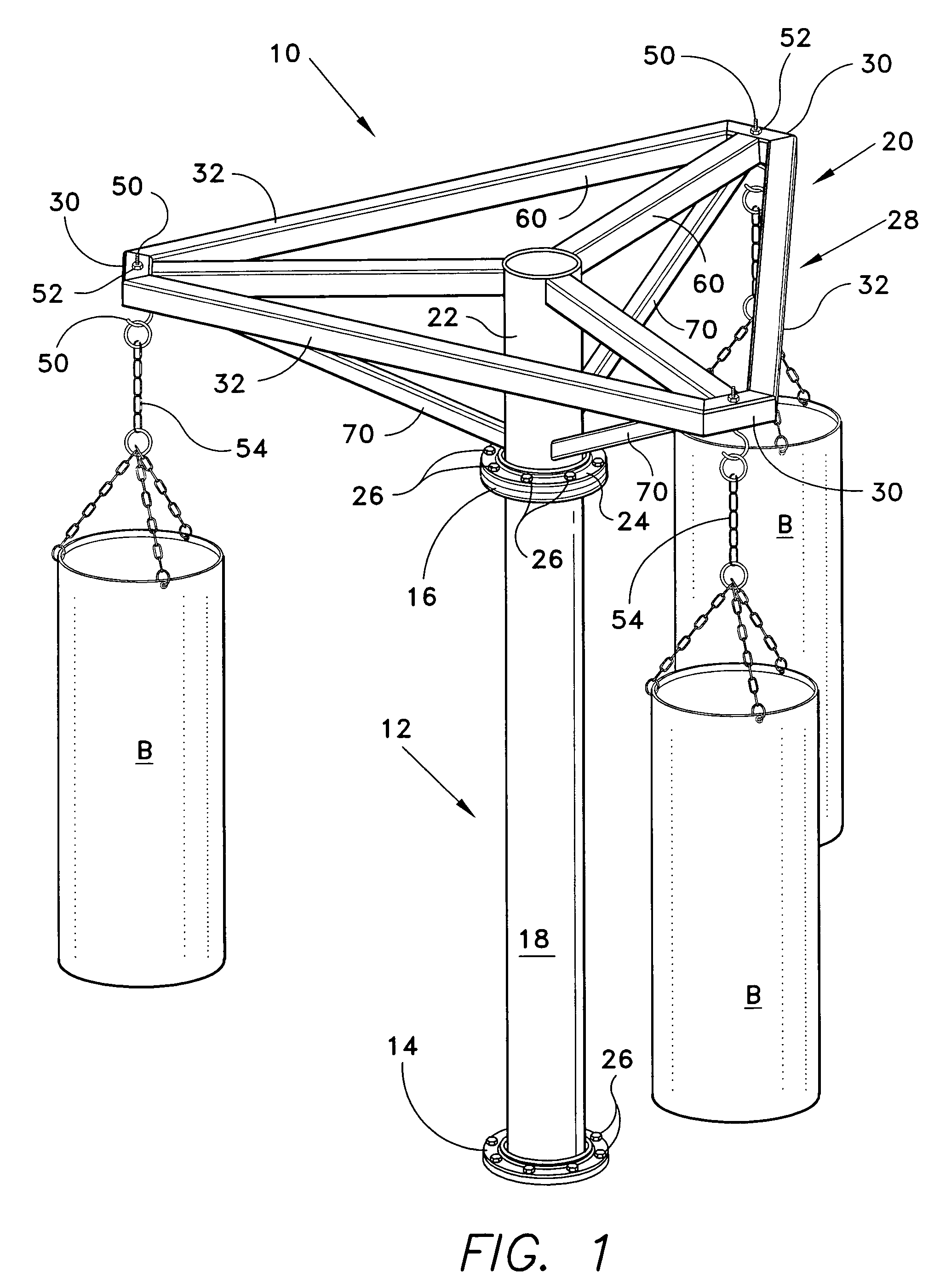
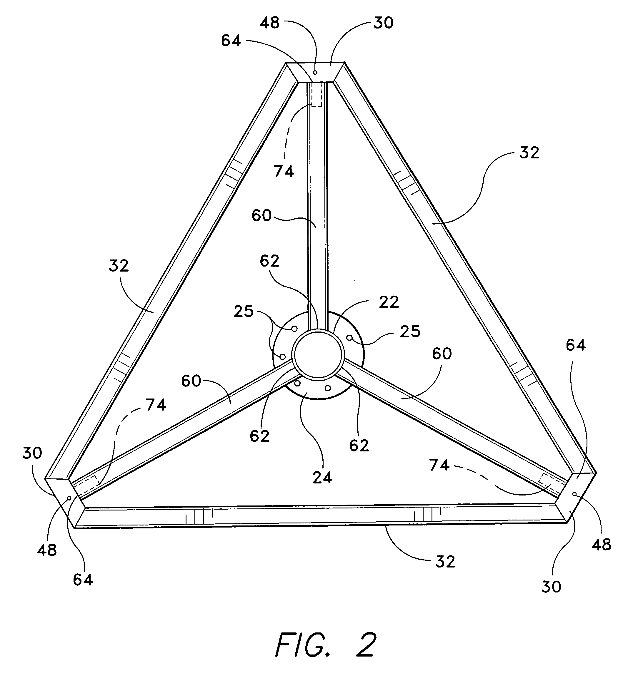
[0006] The multiple heavy bag stand of the present invention is useful for the spaced suspension of heavy boxing bags for use in training boxers. The stand has a centrally disposed, vertically extending stanchion of steel pipe upon which is removably attached a horizontally extending support rack. The rack is constructed of steel tubing of square cross section and forms a polygonal perimeter having a support for an individual bag at each corner of the polygon. Radial supports extend outward from a centrally located vertical support attached at the upper end of the vertical stanchion, the radial supports supporting the polygonal perimeter. A pair of upper horizontal and upper angled lower radial supports is spaced along and extends from the centrally located vertical support to join at each individual bag support. The design is robust to carry the weight of the heavy bags. Boxing bags may be of the same size or of varying sizes as desired. The inventive stand may also be used as a support for a plurality of water bags for a military installation. Support racks having three, four, five, six, eight, of other desired number of bag attachment stations are provided and may be easily replaced or substituted by removing one size from the stanchion and attaching another in its place.

Problems solved by technology

These stands are typically limited to supporting a single boxing bag from a single cantilevered beam.
Such designs are inherently subject to bending and failure during extended use.
The unbalanced design also requires a large base support.

Method used


Image

  • Multiple heavy bag stand
  • Multiple heavy bag stand
  • Multiple heavy bag stand

Examples


Embodiment Construction

[0017] The present invention is a stand for heavy bags such as punching bags or water bags.

[0018] Referring to the Figures, bag stand system 10 includes a vertically disposed, elongated stanchion 12 having a lower stanchion mounting flange 14 for anchoring to a floor and an upper mounting flange 16 at corresponding lower and upper ends of elongate body 18. Preferably, stanchion elongate body 18 is cylindrical in form having a round lower flange having securing bolts 26 set in concrete or otherwise attached to the floor. Stanchion 12 supports a bag support frame 20 having a vertically disposed inner elongate body 22. Elongate body 22 preferably is cylindrical in form having an attachment flange24 at its lower end having bolt receiving bores 25 and being of the same size and bore configuration of stanchion upper mounting flange 16 for attachment therebetween by securing bolts 26 and nuts (not shown). Stanchion 12 and elongate body 22 forms a central post having an upper portion for m...


PUM


Abstract

A stand for the spaced suspension of multiple heavy boxing bags for use in training boxers has a centrally disposed, vertically extending stanchion of steel pipe upon which is fixedly attached a horizontally extending support rack. The rack is square steel tubing forming a polygonal perimeter having a support for an individual bag at each corner of the polygon. Radial supports extend outward from a centrally located vertical support attached at the upper end of the vertical stanchion, the radial supports supporting the polygonal perimeter. A pair of upper horizontal and upper angled lower radial supports are spaced along and extend from the centrally located vertical support to join at each individual bag support. Boxing bags may be of the same size or of varying sizes as desired. The inventive stand may also be used as a support for a plurality of water bags for a military installation.

Description

BACKGROUND OF THE INVENTION [0001] 1. Field of the Invention [0002] The present invention relates to apparatus for supporting athletic exercise equipment or other heavy items. More particularly, the present invention relates to apparatus for supporting a plurality of spaced heavy boxing bags or water bags. [0003] 2. Description of the Related Art [0004] The use of various types of stands for suspending heavy boxing bags for training by a boxer is known. These stands are typically limited to supporting a single boxing bag from a single cantilevered beam. Such designs are inherently subject to bending and failure during extended use. The unbalanced design also requires a large base support. It would be desirable to provide a robust stand capable of suspending a plurality of heavy boxing bags for use by training boxers. It would also be desirable to provide a balanced support stand requiring a minimum of base support. [0005] None of the above-discussed support stands, taken either sing...

Claims


Application Information

Patent Timeline
IPC IPC(8): A63B69/34A63B69/22A63B69/24
CPCA63B69/201A63B71/023A63B69/305
Inventor VALENTINE, ROBERT R.
Owner VALENTINE ROBERT R
Learn More