
Wire guide holder with wire guide deflector

a wire guide and deflector technology, applied in the field of medical procedures, can solve the problems of shifting focus, cumbersome and require constant manipulation, and a multitude of significant drawbacks of prior art devices, and achieve the effect of reducing the number of wire guide holders

Inactive Publication Date: 2006-08-31
WILSONCOOK MEDICAL
View PDF77 Cites 99 Cited by
  • Summary
  • Abstract
  • Description
  • Claims
  • Application Information

AI Technical Summary

Benefits of technology

[0014] According to another aspect of the present invention, a wire guide holder having a wire guide deflector is provided. The wire guide holder is provided with a securing portion and a deflecting portion. The securing portion is configured to secure a distal portion of a wire guide against longitudinal movement. The deflecting portion is configured to direct the proximal end of a wire guide into an unobtrusive position. A frictional element may be provided to prevent the wire guide from inadvertently sliding or falling out of the deflecting portion.

Problems solved by technology

Because of the substantial length of wire guides, they can be cumbersome and require constant, delicate manipulation by a physician.
Due to the complexity of these procedures, physicians often need the assistance of another person to hold the endoscope, manipulate the catheter, and / or hold the wire guide.
However, this shifts the focus of the assistant from their other areas of responsibility, such as checking the patient, checking monitors for relevant information, or carrying out other tasks.
Such prior art devices, however, have a multitude of significant drawbacks.
One drawback is that the wire guide is often damaged by available wire locking devices.
Specifically, the act of jamming or wedging a wire guide into the locking slot can damage or strip the wire guide, thereby rendering wire guide unfit for use.
Such a force can easily kink, strip, or deform the wire guide.
In addition, it is difficult to determine if the wire guide has been properly seated and locked in the locking slot.
As a consequence, the physician may pull of the wire guide to “test” whether it will move relative to the device, which may further damage or strip the wire guide.
Another drawback is that previously available locking devices utilize a small, J-shaped slot to access the wedge portion of the locking device.
However, maneuvering the wire guide is time-consuming and distracting to the physician, and is difficult to perform quickly, effectively, and efficiently during complicated medical procedures.
Another drawback is that previously available locking devices allow the wire guide to extend into the working area of the user, thereby interfering with or distracting the user.

Method used


Image

  • Wire guide holder with wire guide deflector
  • Wire guide holder with wire guide deflector
  • Wire guide holder with wire guide deflector

Examples


Embodiment Construction

[0062] The invention is described with reference to the drawings in which like elements are referred to by like numerals. The relationship and functioning of the various elements of this invention are better understood by the following detailed description. However, the embodiments of this invention as described below are by way of example only, and the invention is not limited to the embodiments illustrated in the drawings. It should also be understood that the drawings are not to scale and in certain instances details have been omitted, which are not necessary for an understanding of the present invention, such as conventional details of fabrication and assembly.

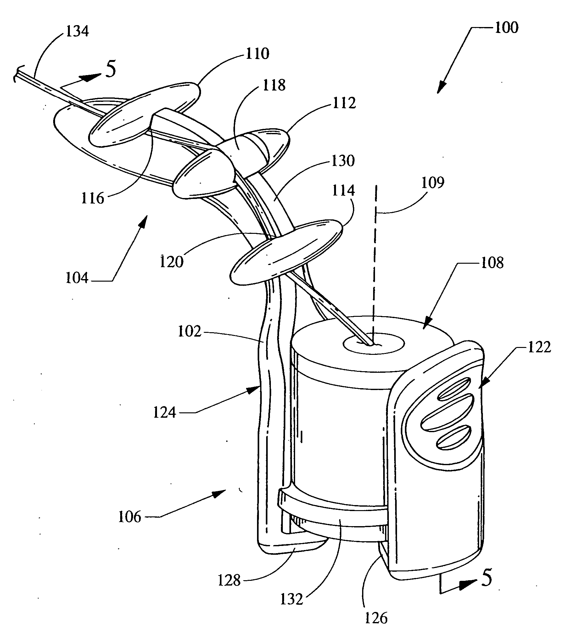
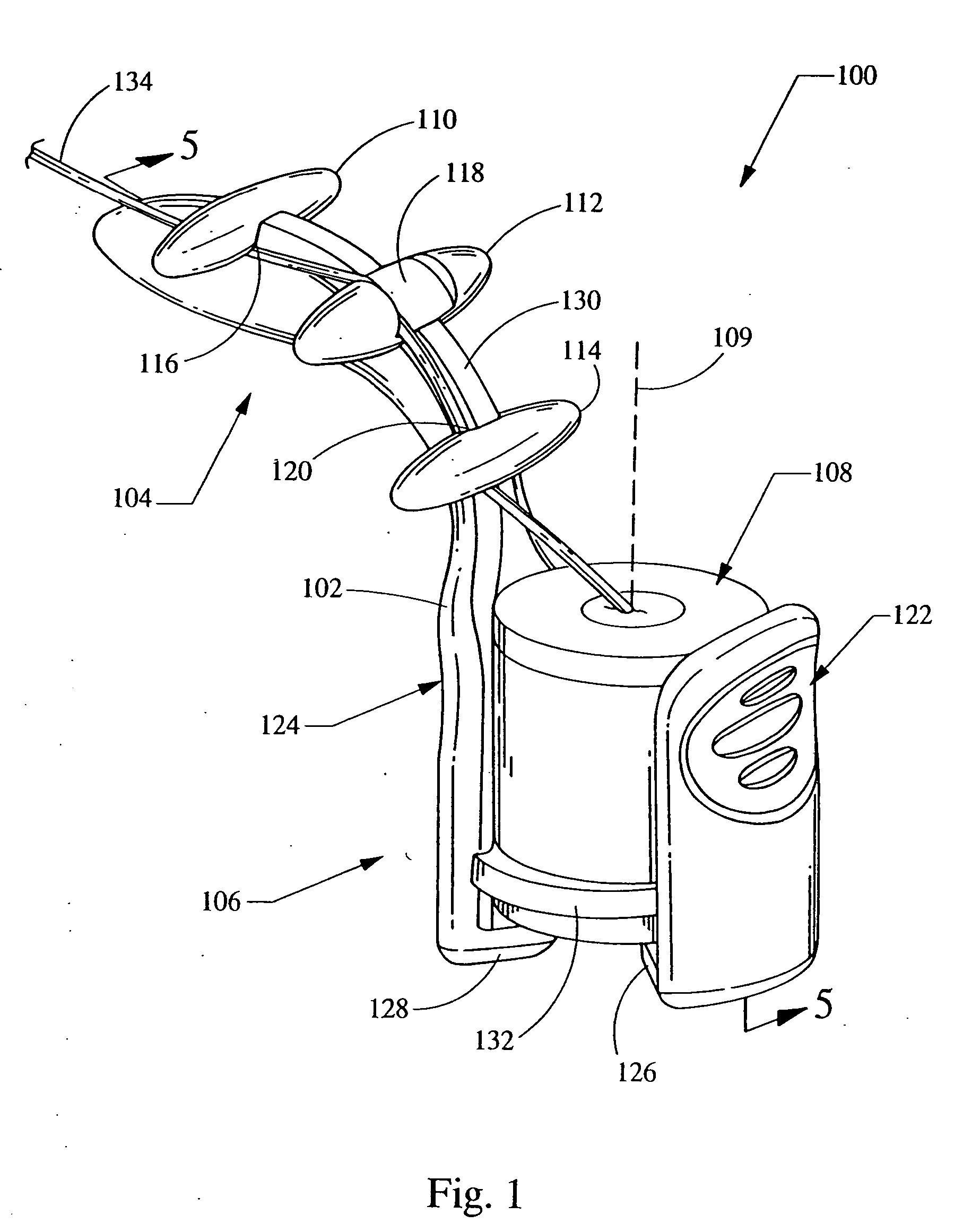
[0063] In general, FIG. 1 illustrates a wire guide holder 100 having a holder body 102, a wire holder 104, and a seal holder 106 enclosing a seal 108. In addition, the wire holder 104 has three spaced apart posts 110, 112, 114, each of which extend generally perpendicularly from a central spine 130. Posts 110, 112, 114, e...


PUM


Abstract

A wire guide holder having a wire guide deflector. The wire guide holder is provided with a securing portion and a deflecting portion. The securing portion is provided with protrusions and / or grooves for securing a distal portion of a wire guide against longitudinal movement. The deflecting portion is configured to direct the proximal end of a wire guide into an unobtrusive position. A frictional element may be provided to prevent the wire guide from inadvertently sliding or falling out of the deflecting portion. The wire guide holder may be attached to a medical scope or a bite block. The wire guide holder may also be provided with a seal.

Description

RELATED APPLICATIONS [0001] This application is a continuation-in-part of U.S. patent application Ser. No. 10 / 903,679, filed Jul. 29, 2004, which claims the benefit of U.S. Provisional Application No. 60 / 571,142, filed May 14, 2004, U.S. Provisional Application No. 60 / 570,656, filed May 13, 2004, U.S. Provisional Application No. 60 / 565,030, filed Apr. 23, 2004, U.S. Provisional Application No. 60 / 563,968, filed Apr. 21, 2004, and U.S. Provisional Application No. 60 / 491,408, filed Jul. 31, 2003. This application also claims the benefit of U.S. Provisional Application No. 60 / 651,748, filed Feb. 10, 2005.BACKGROUND OF THE INVENTION [0002] The invention is useful in the area of medical procedures, particularly medical procedures involving an introducer catheter, a wire guide, an endoscope, or the like. [0003] Endoscopes are routinely used to perform various medical procedures in areas of the body that are difficult to visualize or access, or that may otherwise require an open procedure ...

Claims


Application Information

Patent Timeline
Patent Type & Authority Applications(United States)
IPC IPC(8): A61F11/00
CPCA61B1/00137A61B1/012A61M25/01A61M25/09041A61M2025/024A61M2025/028A61M2025/09116A61M2025/09125
Inventor RUCKER, BRIAN K.KENNEDY, KENNETH C. IIWALLER, DAVID F.
Owner WILSONCOOK MEDICAL
Learn More