Method and structure to reduce optical crosstalk in a solid state imager

a solid-state imager and optical crosstalk technology, applied in the field of electromagnetic systems, can solve the problems of increasing the size, complexity and cost of imagers and imager fabrication, affecting the quality of imagers, and reducing the efficiency of imagers, so as to achieve more compact pixel construction

Active Publication Date: 2006-09-07
MICRON TECH INC
View PDF1 Cites 28 Cited by
  • Summary
  • Abstract
  • Description
  • Claims
  • Application Information

AI Technical Summary

Benefits of technology

[0012] Advantageously, if the conserved section of the polysilicon layer used for light shielding, it is located adjacent an energy-admitting face of the photosensor. The close proximity of the light shields formed by the conserved sections of the polysilicon layer prevent scattering of light to neighboring pixels. The light shields thus formed make economical and valuable use of material previously considered waste. The conserved section, of the polysilicon layer for example, may also be used for light collection purposes. The conserved sections of an existing layer can be used to replace or augment the functions of other layers, which other layers accordingly can be removed or made thinner, resulting in a more compact pixel construction.

Problems solved by technology

Optical crosstalk in imagers can bring about undesirable results in images that they produce.
The undesirable results can become more pronounced as the density of pixels in imager arrays increases, and as pixel size correspondingly decreases.
The added layers of light shields, however, increase the size, complexity, and cost of imagers and imager fabrication.
Light shields formed in such upper fabrication layers have inherent drawbacks, however.
For example, metallization layers dedicated to light shielding are limited in their normal use as conductive connections for the imager array.
Moreover, the light shields are imperfect, and allow some light to pass into the light transmitting layers.
Having the light shields spaced apart from the surface of the photosensor also can increase light piping and light shadowing in the photosensors, leading to further errors in imager function.

Method used


Image

  • Method and structure to reduce optical crosstalk in a solid state imager
  • Method and structure to reduce optical crosstalk in a solid state imager
  • Method and structure to reduce optical crosstalk in a solid state imager

Examples


Embodiment Construction

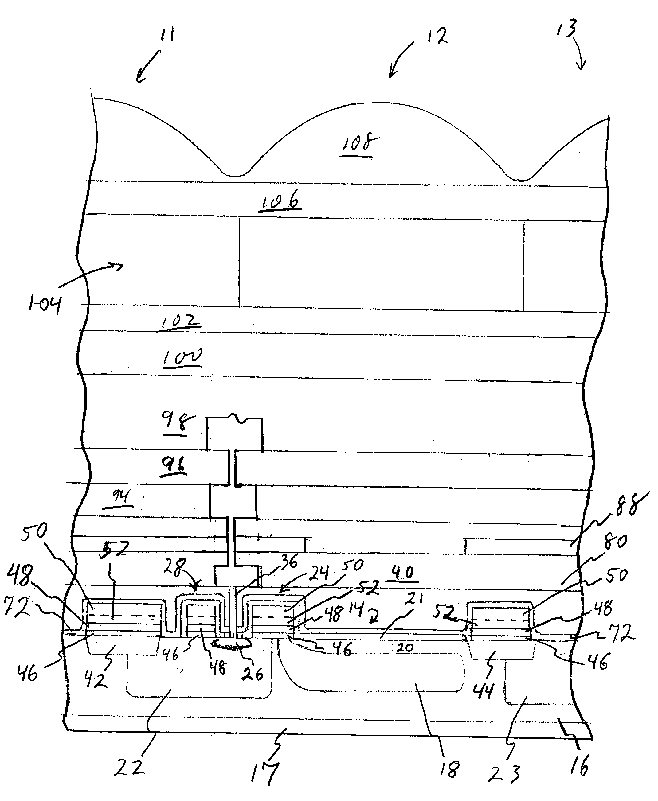
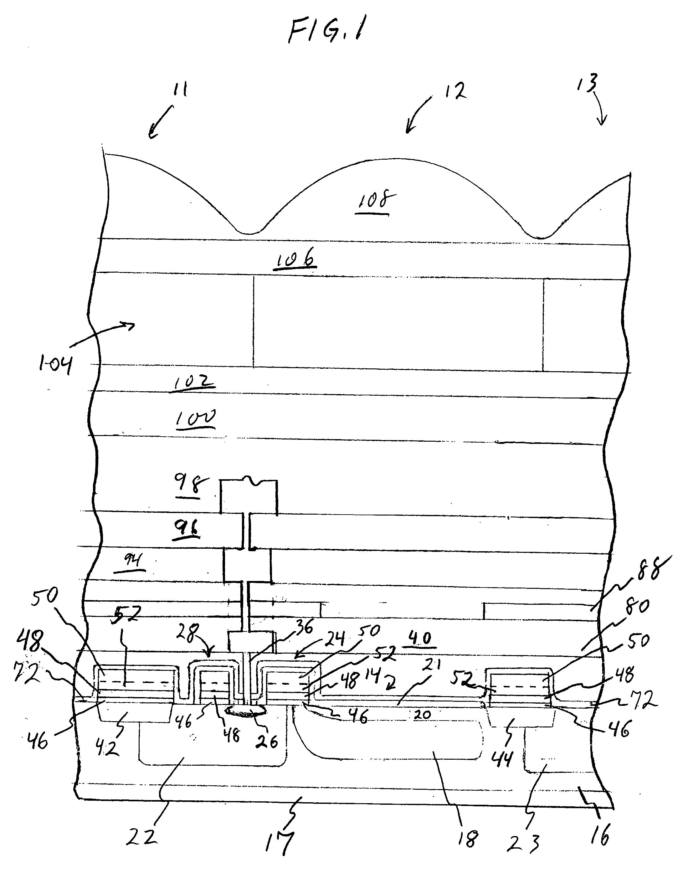
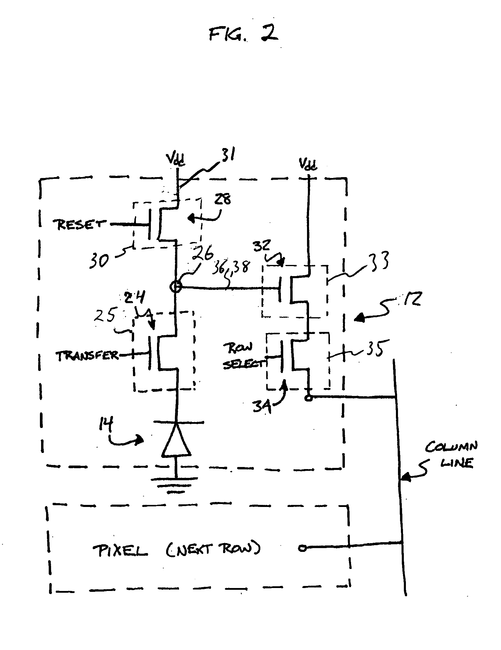
[0028] In the following detailed description, reference is made to the accompanying drawings which form a part hereof and illustrate specific exemplary embodiments by which the invention may be practiced. It should be understood that like reference numerals represent like elements throughout the drawings. These embodiments are described in sufficient detail to enable those skilled in the art to practice the invention. It is to be understood that other embodiments may be utilized, and that structural, logical, and electrical changes may be made without departing from the spirit and scope of the present invention.

[0029] The term “substrate” is to be understood as including silicon-on-insulator (SOI) or silicon-on-sapphire (SOS) technology, doped and undoped semiconductors, epitaxial layers of silicon supported by a base semiconductor foundation, and other semiconductor structures. Furthermore, when reference is made to a “substrate” in the following description, previous process step...


PUM


Abstract

Methods and structures to reduce optical crosstalk in solid state imager arrays. Sections of pixel material layers that previously would have been etched away and disposed of as waste during fabrication are left as conserved sections. These conserved sections are used to amend the properties and performance of the imager array. In the resulting structure, the conserved sections absorb incident light. The patterned portions of conserved material provide additional light shielding for array pixels.

Description

FIELD OF THE INVENTION [0001] This invention generally relates to electronic systems and in particular it relates to semiconductor image sensing devices. BACKGROUND OF THE INVENTION [0002] Optical crosstalk may exist between neighboring photosensors in a pixel array of a solid state imager, such as a CCD or CMOS imager, for example. Optical crosstalk in imagers can bring about undesirable results in images that they produce. The undesirable results can become more pronounced as the density of pixels in imager arrays increases, and as pixel size correspondingly decreases. [0003] In an idealized photosensor, a photodiode for example, light enters only through the surface of the photodiode that directly receives the light stimulus. In reality, however, light intended for neighboring photosensors also enters the photodiode, in the form of stray light, through the sides of the photosensor structure for example. Reflection and refraction within the photosensor structure can give rise to t...

Claims


Application Information

Patent Timeline
Patent Type & Authority Applications(United States)
IPC IPC(8): H01L27/14
CPCH01L27/14609H01L27/14623H01L27/1463H01L27/14632H01L27/14683H01L27/14685H01L27/14687H01L27/14689
Inventor COLE, BRYAN G.
Owner MICRON TECH INC
Why Eureka
Try Eureka