
Touch panel and method of manufacturing the same

a technology of touch panel and manufacturing method, which is applied in the field of interactive display system, can solve the problem of distorted and achieve the effect of improving the visual quality of displayed images

Active Publication Date: 2006-09-07
SMART TECH INC (CA)
View PDF14 Cites 52 Cited by
  • Summary
  • Abstract
  • Description
  • Claims
  • Application Information

AI Technical Summary

Benefits of technology

[0019] The touch panel provides advantages in that, by using an input registration structure disposed on a generally inflexible cover that defines a touch surface opposite the input registration structure, the palm reject issues associated with conventional analog-resistive type touch panels are avoided. Additionally, accidental contact with the touch surface does not result in erroneous input being registered.

Problems solved by technology

Although PCs and PDAs are widely accepted, as the touch panel is disposed over the display the visual quality of displayed images can be somewhat distorted.

Method used


Image

  • Touch panel and method of manufacturing the same
  • Touch panel and method of manufacturing the same
  • Touch panel and method of manufacturing the same

Examples


Embodiment Construction

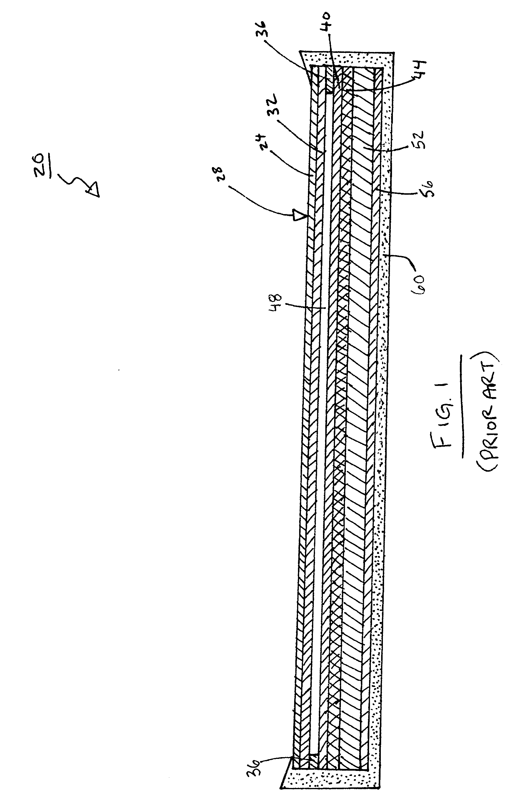
[0032] For ease of understanding, a prior art touch panel of the analog-resistive type will firstly be described. Turning now to FIG. 1, a prior art touch panel is shown and is generally identified by reference numeral 20. The touch panel 20 is generally rectangular and includes an upper planar tensioned membrane 24. The upper surface of the tensioned membrane 24 defines a generally smooth touch surface 28. A conductive resistive layer 32 is applied to the undersurface of the tensioned membrane 24. A peripheral insulating spacer 36 spaces the resistive layer 32 from another conductive resistive layer 40 that is applied to the top surface of a rigid protective layer 44 to provide an air gap 48. The tension applied to the tensioned membrane 24 in conjunction with spacer 36 maintains separation between the resistive layer 32 and the resistive layer 40 in the absence of pointer contacts on the touch surface 28. The rigid protective layer 44 is disposed above a display panel 52. Each of ...


PUM


Abstract

A touch panel includes an input registration structure comprising a biasable medium layer. A generally inflexible cover is disposed on the input registration structure and defines a touch surface. A pointer biases the biasable medium layer at a position adjacent the pointer when the pointer is positioned proximate the touch surface. The input registration structure generates a position signal corresponding to the position of the pointer in relation to the touch surface.

Description

FIELD OF THE INVENTION [0001] The present invention relates generally to interactive display systems and, more particularly, to a touch panel and method of manufacturing the same. BACKGROUND OF THE INVENTION [0002] Touch panels, such as for example digitizers and analog resistive touch screens are known in the art. These touch panels typically include a conductive tensioned membrane defining a touch surface that is stretched tautly over and spaced from a conductive substrate. When a pointer is used to contact the tensioned membrane with sufficient activation force, the tensioned membrane deflects and contacts the conductive substrate thereby to make an electrical contact. Determining voltage changes induced by the electrical contact allows the position of pointer contact on the touch surface to be determined and a position signal corresponding to the position of pointer contact to be generated. [0003] Touch panels of this nature are often used in conjunction with a display such as a...

Claims


Application Information

Patent Timeline
Patent Type & Authority Applications(United States)
IPC IPC(8): G09G5/00
CPCG06F3/041G06F3/045
Inventor POPOVICH, DAVID GREGORY
Owner SMART TECH INC (CA)
Features
  • Generate Ideas
  • Intellectual Property
  • Life Sciences
  • Materials
  • Tech Scout
  • Unparalleled Data Quality
  • Higher Quality Content
  • 60% Fewer Hallucinations
Learn More