Control circuit for a depletion mode switch and method of operating the same

a control circuit and depletion mode technology, applied in the field of power electronics, can solve the problems of imposing challenges on the design of power supplies, high frequency operation, and affecting the efficiency of power converters, and achieving the effect of facilitating the construction of a true enhancement mode mos

Active Publication Date: 2006-09-07
MYPAQ HLDG LTD
View PDF99 Cites 112 Cited by
  • Summary
  • Abstract
  • Description
  • Claims
  • Application Information

AI Technical Summary

Benefits of technology

[0010] These and other problems are generally solved or circumvented, and technical advantages are generally achieved, by advantageous embodiments of the present invention that include a control circuit for a power converter employing a depletion mode switch and a method of operating the same. In one embodiment, the control circuit includes a controller configured to control the depletion mode switch by providing a drive signal to a control terminal thereof as a function of a characteristic of the power converter. The control circuit also includes a protection circuit configured to induce an application of a drive signal having a non-zero value to the control terminal to substantially disable the depletion mode switch in response to a transient condition of the power converter.

Problems solved by technology

Advances in microprocessors and other electronic technologies impose challenges in the design of the power supplies required to meet increasingly stringent power requirements thereof.
The high frequency operation, however, can have a detrimental effect on the efficiency of the power converter, as a significant amount of power is necessary to drive the control terminals of the switches such as the gate terminals of metal-oxide semiconductor field-effect transistors (“MOSFETs”) at higher frequencies.
The lack of a native oxide for many of the group III-V semiconductor devices makes the construction of a true enhancement mode MOSFET difficult.
While the application of a negative gate-to-source voltage is somewhat straightforward during steady state operation of the power converter employing such a switch, the requirement for a negative gate-to-source voltage may be problematic during non-steady state operations of the power converter or when the converter and switch are subject to transient conditions.

Method used


Image

  • Control circuit for a depletion mode switch and method of operating the same
  • Control circuit for a depletion mode switch and method of operating the same
  • Control circuit for a depletion mode switch and method of operating the same

Examples


Embodiment Construction

[0023] The making and using of the presently preferred embodiments are discussed in detail below. It should be appreciated, however, that the present invention provides many applicable inventive concepts that can be embodied in a wide variety of specific contexts. The specific embodiments discussed are merely illustrative of specific ways to make and use the invention, and do not limit the scope of the invention. Unless otherwise provided, like designators for devices employed in different embodiments illustrated and described herein do not necessarily mean that the similarly designated devices are constructed in the same manner or operate in the same way. It should also be understood that the use of the terms such as “first” and “second” are employed for purposes of explanation and clarity, and reversing such designations when referring to device(s) is well within the broad scope of the present invention.

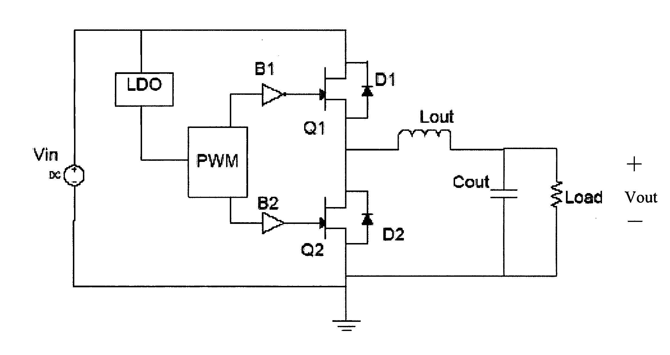
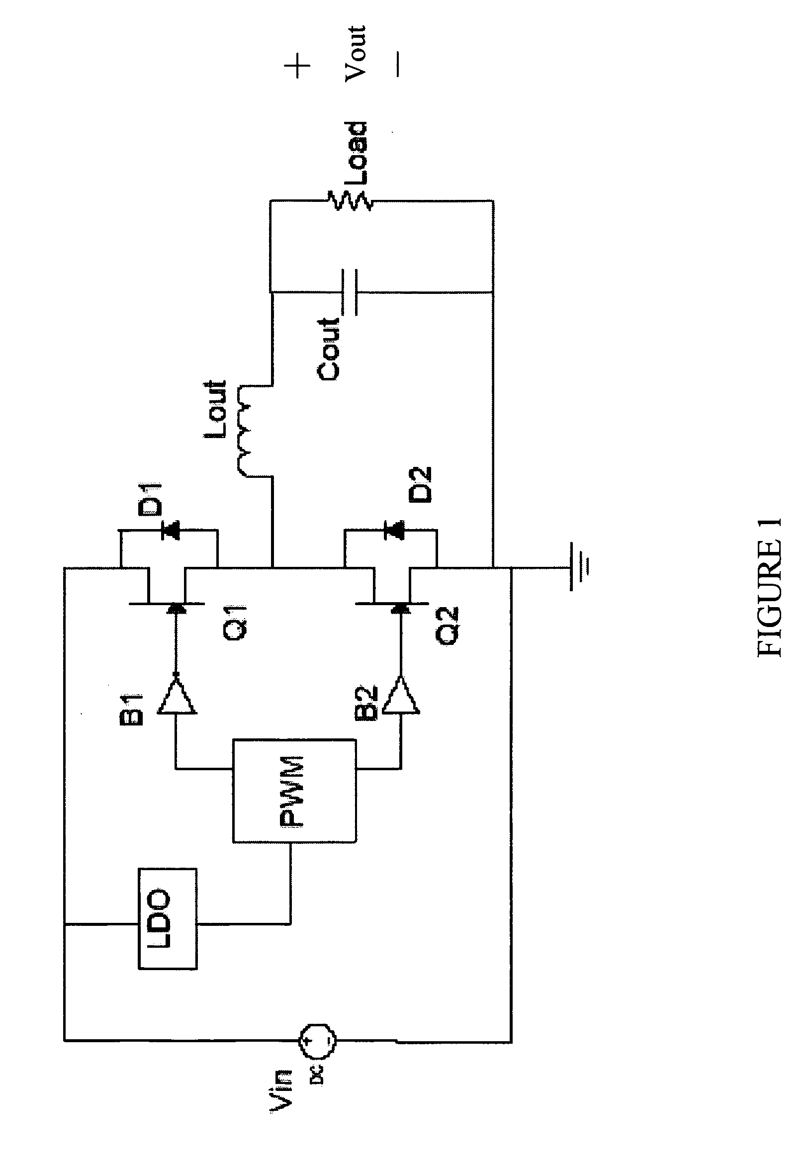
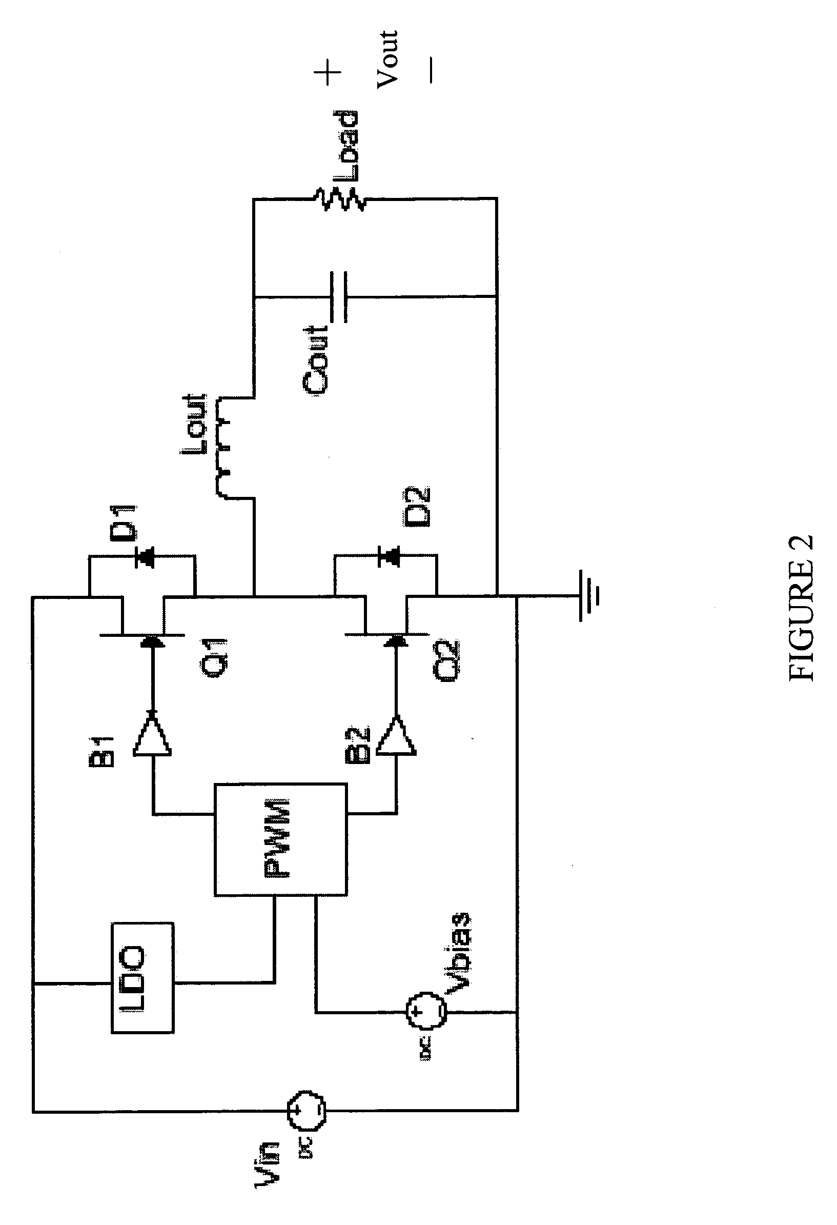
[0024] The invention will be described with respect to an exemplary embodimen...


PUM


Abstract

A control circuit for a power converter employing a depletion mode switch and a method of operating the same. In one embodiment, the control circuit includes a controller configured to control the depletion mode switch by providing a drive signal to a control terminal thereof as a function of a characteristic of the power converter. The control circuit also includes a protection circuit configured to induce an application of a drive signal having a non-zero value to the control terminal to substantially disable the depletion mode switch in response to a transient condition of the power converter.

Description

[0001] This application claims the benefit of U.S. Provisional Application Ser. No. 60 / 655,313, entitled “Circuit and Method for Protecting a Switching Device,” filed on Feb. 23, 2005, which is incorporated herein by reference.TECHNICAL FIELD [0002] The present invention is directed, in general, to power electronics and, in particular, to a control circuit for a power converter employing a depletion mode switch and method of operating the same. BACKGROUND [0003] A switched-mode power converter (also referred to as a “power converter”) is an electronic power processing circuit that converts an input voltage waveform into an output voltage waveform. The waveforms are typically, but not necessarily, dc waveforms, controlled by periodically switching power switches or switches coupled to an inductive circuit element. The switches are generally controlled with a conduction period “D” referred to as a “duty cycle.” The duty cycle is a ratio represented by the conduction period of a switch...

Claims


Application Information

Patent Timeline
Patent Type & Authority Applications(United States)
IPC IPC(8): H02M7/00
CPCH02M1/08H03K17/08122H03K17/6871H03K17/6874H03K2017/6875
Inventor ROZMAN, ALLEN F.
Owner MYPAQ HLDG LTD
Why Eureka
Try Eureka