
Cutting tool and parts and accessories therefor

a cutting tool and cutting blade technology, applied in the field of cutting tools, can solve the problems of difficult to focus, difficult to remove and replace the saw blade, and the tool is not designed to allow easy attachment, removal and replacement of the saw blade,

Inactive Publication Date: 2006-09-14
JPW IND
View PDF56 Cites 34 Cited by
  • Summary
  • Abstract
  • Description
  • Claims
  • Application Information

AI Technical Summary

Problems solved by technology

For example, one common shortcoming with conventional cutting tools is that the tools are not designed to allow for easy attachment, removal and replacement of the saw blade.
This proved difficult to do in that the operator needed to focus on holding and operating both wrenches simultaneously and in close proximity to the saw blade.
Conventional blade locks, however, only hold the saw blade, rather than the blade and the arbor.
Other shortcomings associated with such blade locks include the fact that the blade lock itself can be misplaced or lost, can wear to the point the blade is not securely stopped from rotation, and can be difficult to operate with one hand while the operator tries to operate a wrench with his or her other hand.
Unfortunately, these arbor lock systems often require intricate mechanical components and additional structures or framework to be added to the cutting tool.
They also typically crowd the opening in the work surface through which the saw blade extends making it more difficult to reach into the table opening and install, remove or replace the saw blade.
In addition, some of these arbor lock systems can increase the possibility of the arbor lock being inadvertently actuated due to their automatic operation, which can cause serious damage to the cutting tool.
Another shortcoming with respect to conventional cutting tools is that the tools are heavy and not easy to move.
This is particularly burdensome when the tool is placed in a crowded or small workshop where space is at a premium and tools must be moved often.
Although these wheel attachments have succeeded in making the tool more mobile, they do not allow the tool or tool housing to rest firmly on the floor once it has been moved into a desired position and often allow the tool to wobble due to movement permitted by the wheels, even when the wheels are locked.
Unfortunately, however, these lift mechanisms are incapable of lifting heavy power tools, such as cabinet saws, and are incapable of lifting power tools that do not have open stand bases, such as table saws with enclosed (or closed) bases.
Another shortcoming with existing cutting tools is that they lack internal storage space for holding equipment that may be used in conjunction with the cutting tool.
This lack of storage space, often leads to the equipment being lost or misplaced and / or not readily available when needed.
Unfortunately, however, these remote external storage compartments are often considered optional equipment that the operator must pay for in addition to the expense of the cutting tool itself.
Most of these storage compartments also require separate assembly and attachment to the cutting tool which makes initial setup of the cutting tool longer and more burdensome on the operator.
Unfortunately, however, these integral external storage compartments are exposed to the workshop environment and often collect sawdust and other airborne particles causing the storage compartments to fill up and making it harder to use the storage compartments for their intended purpose.
In addition, existing cutting tools, with or without integral external storage compartments or remote external storage compartments, waste a large amount of interior space which is particularly problematic in smaller workshops where every bit of space is extremely valued.
Another shortcoming with existing cutting tools is that they fail to keep track of blade angles that may be routinely used by the operator.
For example, traditional cutting tools provide a blade angle scale so that an operator can quickly adjust the saw blade to a desired position; however, they do not allow the operator to keep track of angles that have been repetitively used in order to assist the operator in returning the saw blade to such angles.
This is particularly problematic when an operator has to adjust the angle of the saw blade multiple times during a project and wishes to return to at least one of the angles multiple times.
Another problem with conventional cutting tools is that the extensions that are provided with the table saw often take up a large amount of workshop space but provide little use outside of simply supporting workpieces that are being cut via the cutting tool.
For example, conventional table extensions are often too delicate to be used for other workshop purposes.

Method used


Image

  • Cutting tool and parts and accessories therefor
  • Cutting tool and parts and accessories therefor
  • Cutting tool and parts and accessories therefor

Examples


Embodiment Construction

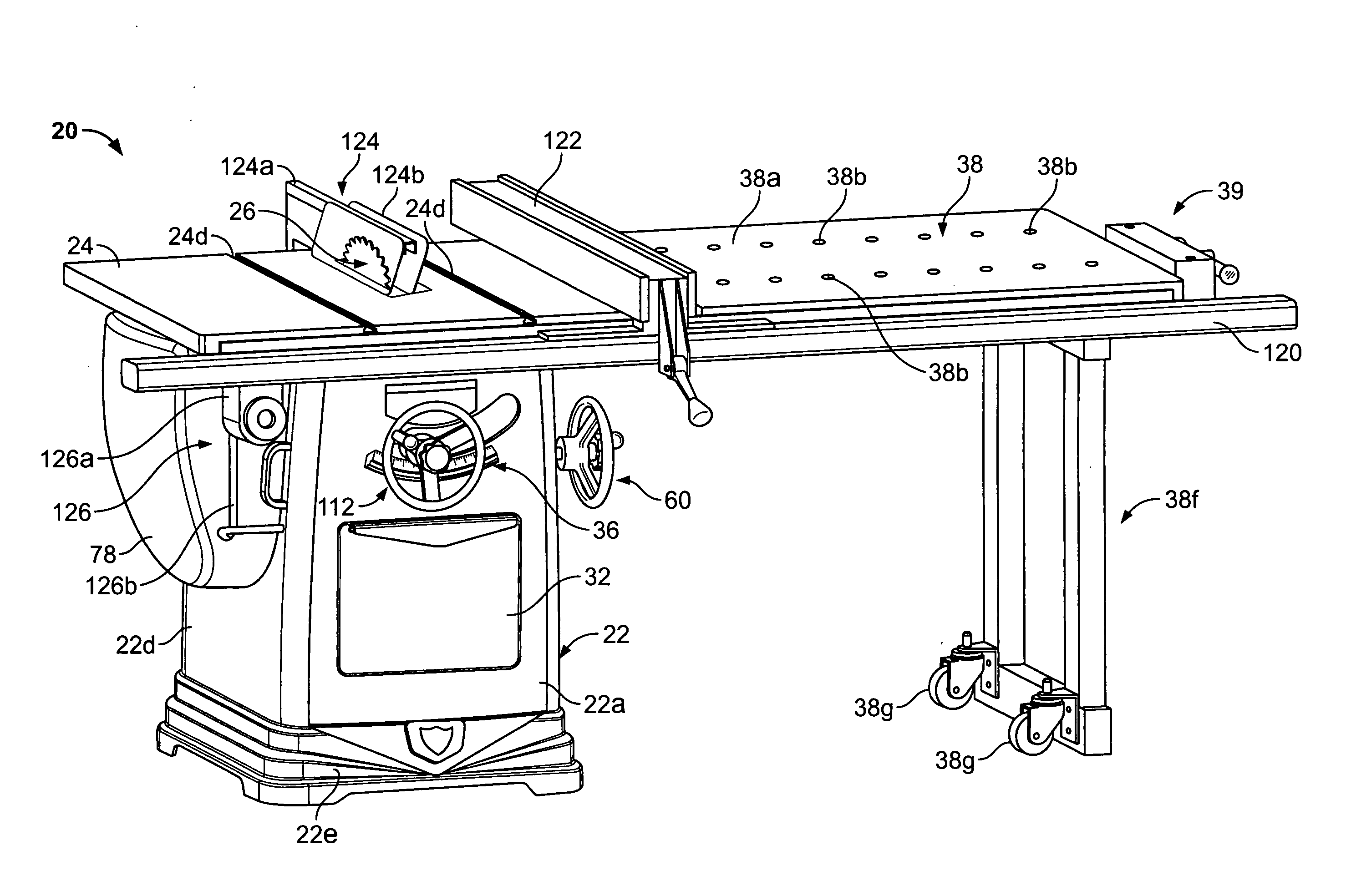
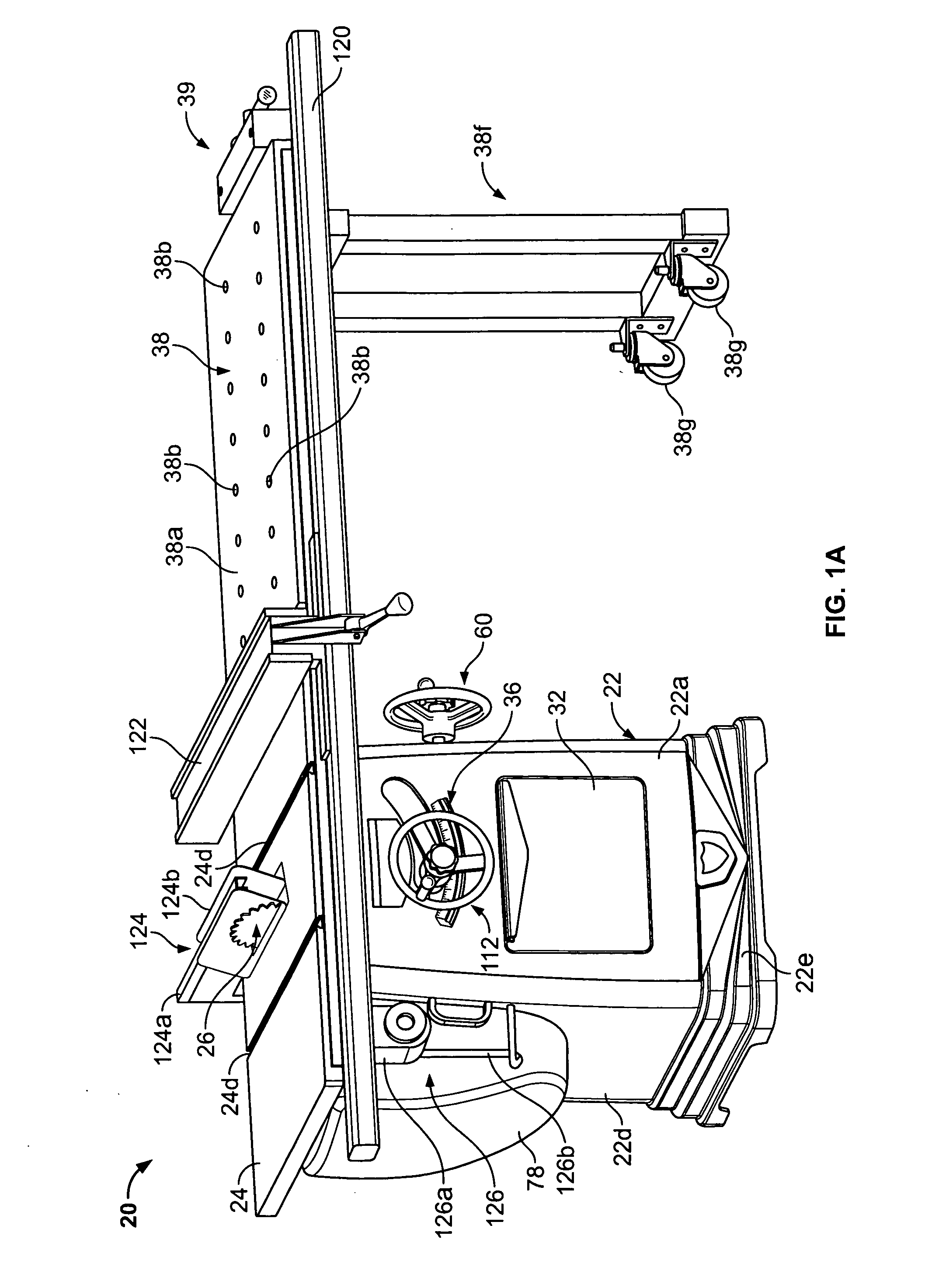
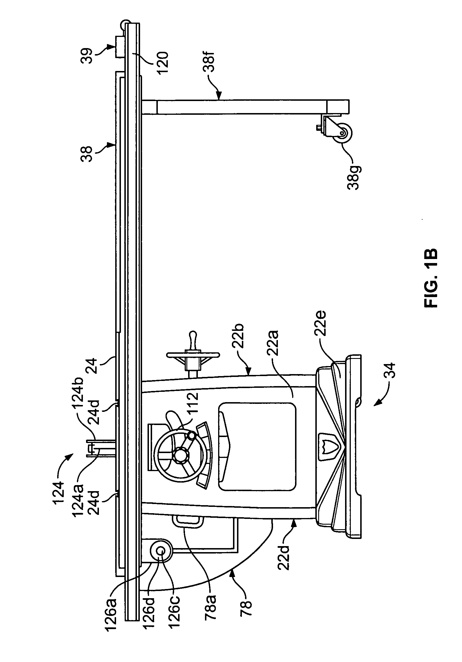
[0042] Turning now to the drawings, in which FIGS. 1A-F illustrate a cutting tool 20 in accordance with the invention, the cutting tool 20 includes a housing 22 with a generally flat work surface, such as table 24, upon which workpieces, such as wood or metal, may be set or rested. The table 24 defines an opening 24a through which a cutting implement, such as saw blade 26, may be disposed. In addition to the conventional components of a cutting tool, cutting tool 20 may also include an arbor lock 28 (FIGS. 7A-E), located within housing 22, for preventing the arbor 30 from rotating to assist an operator in installing, removing or replacing the saw blade 26. The cutting tool 20, may also include an internal storage compartment 32 for storing items or equipment, including those for use in connection with the cutting tool 20, an internal mobility system 34 to assist the operator in moving the cutting tool 20 when desired, and a cutting implement angle memory indicator 36 for aiding the ...


PUM

PropertyMeasurementUnit
Angleaaaaaaaaaa

Abstract

A cutting tool in accordance with the invention may include an arbor lock, located within its housing, for preventing the arbor from rotating to assist an operator in installing, removing or replacing the saw blade. The cutting tool may also include an internal storage compartment for storing items or equipment, including those for use in connection with the cutting tool, an internal mobility system to assist the operator in moving the cutting tool when desired, and a cutting implement angle memory indicator for aiding the operator in keeping track of a desired cutting implement position. The cutting tool may also be provided with a sturdy bench top extension extending out from the cutting tool housing which the operator may use to perform a variety of workshop tasks including some not related to the use of the cutting tool itself.

Description

CROSS-REFERENCE To RELATED APPLICATION [0001] This application claims benefit of United States Provisional Application No. 60 / 660,554, filed Mar. 11, 2005, which is hereby incorporated herein by reference in its entirety.FIELD OF THE INVENTION [0002] This invention relates generally to cutting tools and more particularly relates to a saw and parts and accessories therefor. BACKGROUND OF THE INVENTION [0003] In the tool industry there are several different types of cutting tools, such as, for example, table saws, cabinet saws and contractor saws. These tools typically have housings with generally flat work surfaces forming tables upon which workpieces, such as wood or metal, may be set or rested. The table usually defines an opening through which a cutting implement, such as a saw blade, extends in order to perform work on the workpiece. These tools will also often have table extensions, which are coplanar with the upper surface of the work surface and provide additional support and ...

Claims


Application Information

Patent Timeline
IPC IPC(8): B23D45/06
CPCB23D45/068B23D47/025B27B5/10B27B5/38Y10T83/7705Y10T83/7722Y10T83/7726Y10T83/773
Inventor SCHWAIGER, BARRY M.PHILLIPS, WILLIAM J.
Owner JPW IND
Features
  • Generate Ideas
  • Intellectual Property
  • Life Sciences
  • Materials
  • Tech Scout
  • Unparalleled Data Quality
  • Higher Quality Content
  • 60% Fewer Hallucinations
Learn More