Modular, distributed, ROV retrievable subsea control system, associated deepwater subsea blowout preventer stack configuration, and methods of use

a control system and subsea technology, applied in the field of offshore drilling operations, can solve the problems of requiring dramatic increases in functional capability, and in turn, the complexity of control system operating methodologies and complexity, and the serious effect of system reliability

Active Publication Date: 2006-09-14
OCEANEERING INTERNATIONAL
View PDF34 Cites 19 Cited by
  • Summary
  • Abstract
  • Description
  • Claims
  • Application Information

AI Technical Summary

Problems solved by technology

Recent deepwater development commitments have placed increased demands for well control systems, requiring dramatic increases in the functional capability of subsea BOP Stacks and, in turn, the control system operating methodologies and complexity.
These additional operational requirements and complexities have had a serious effect on system reliability, particularly in the control system components and interface.
Although redundancy provisions are provided by the use of two control pods, a single point failure in either control pod or function interface is considered system failure necessitating securing the well and retrieving the lower marine riser package, containing the control pods, or the complete BOP Stack for repair.
Retrieving any portion of the BOP Stack is time consuming creating “lost revenue” and rig “down time” considering the complete marine riser must be pulled and laid down.
Running and retrieving a subsea BOP Stack in deepwater is a significant event with potential for catastrophic failure and injury risk for personnel involved in the operation.
Substantial increases in the overall weight and size of high pressure BOP Stacks has created problems for drilling contractors who have a high percentage of existing vessels, which will not accommodate these larger stacks without substantial modifications and considerable expense.
In most cases, the larger, heavier and more complex units are requiring by operators for “deep water” applications and reduce the potential for negotiating a contract for the particular rig without this equipment.

Method used


Image

  • Modular, distributed, ROV retrievable subsea control system, associated deepwater subsea blowout preventer stack configuration, and methods of use
  • Modular, distributed, ROV retrievable subsea control system, associated deepwater subsea blowout preventer stack configuration, and methods of use
  • Modular, distributed, ROV retrievable subsea control system, associated deepwater subsea blowout preventer stack configuration, and methods of use

Examples


Embodiment Construction

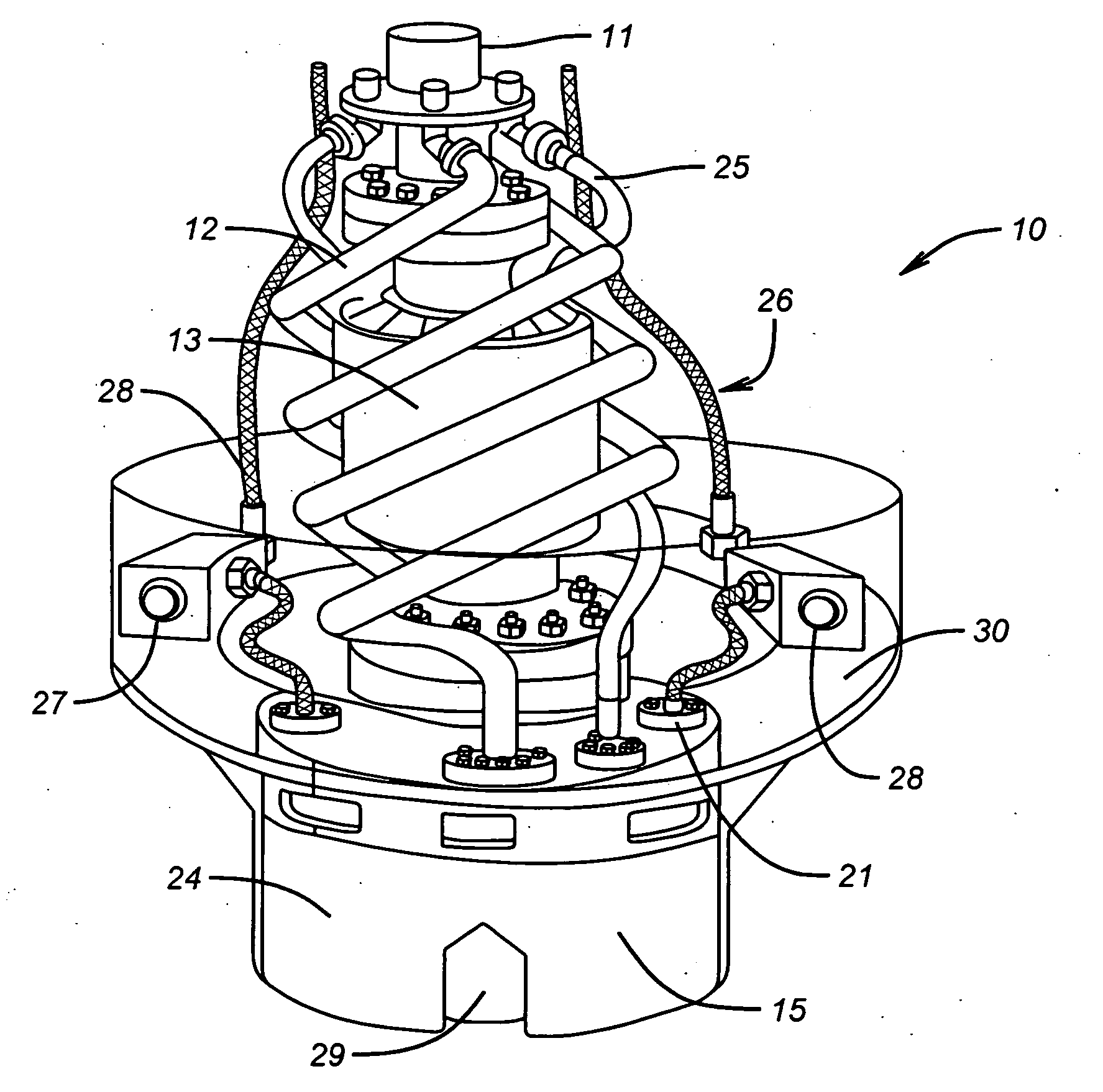
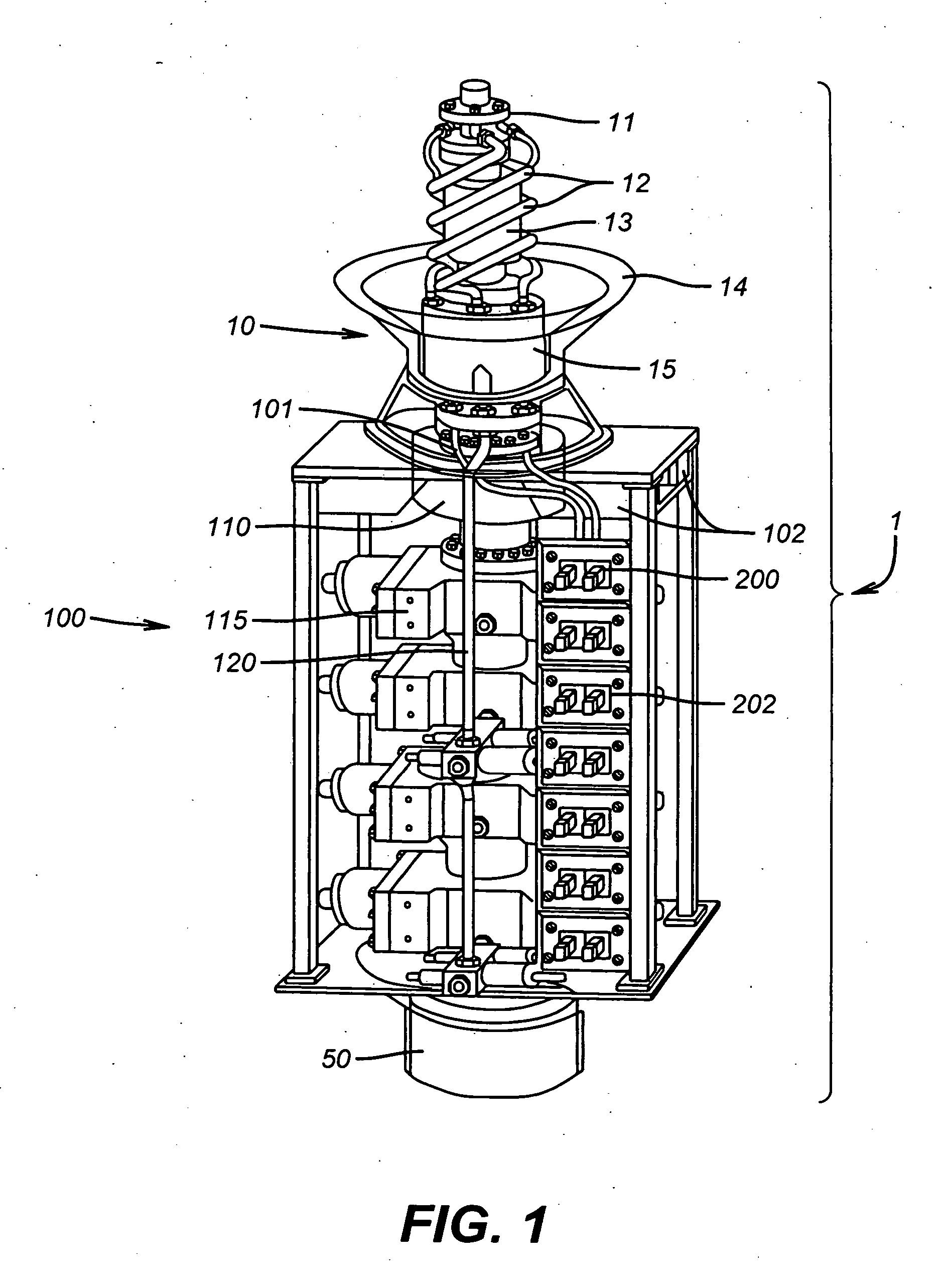
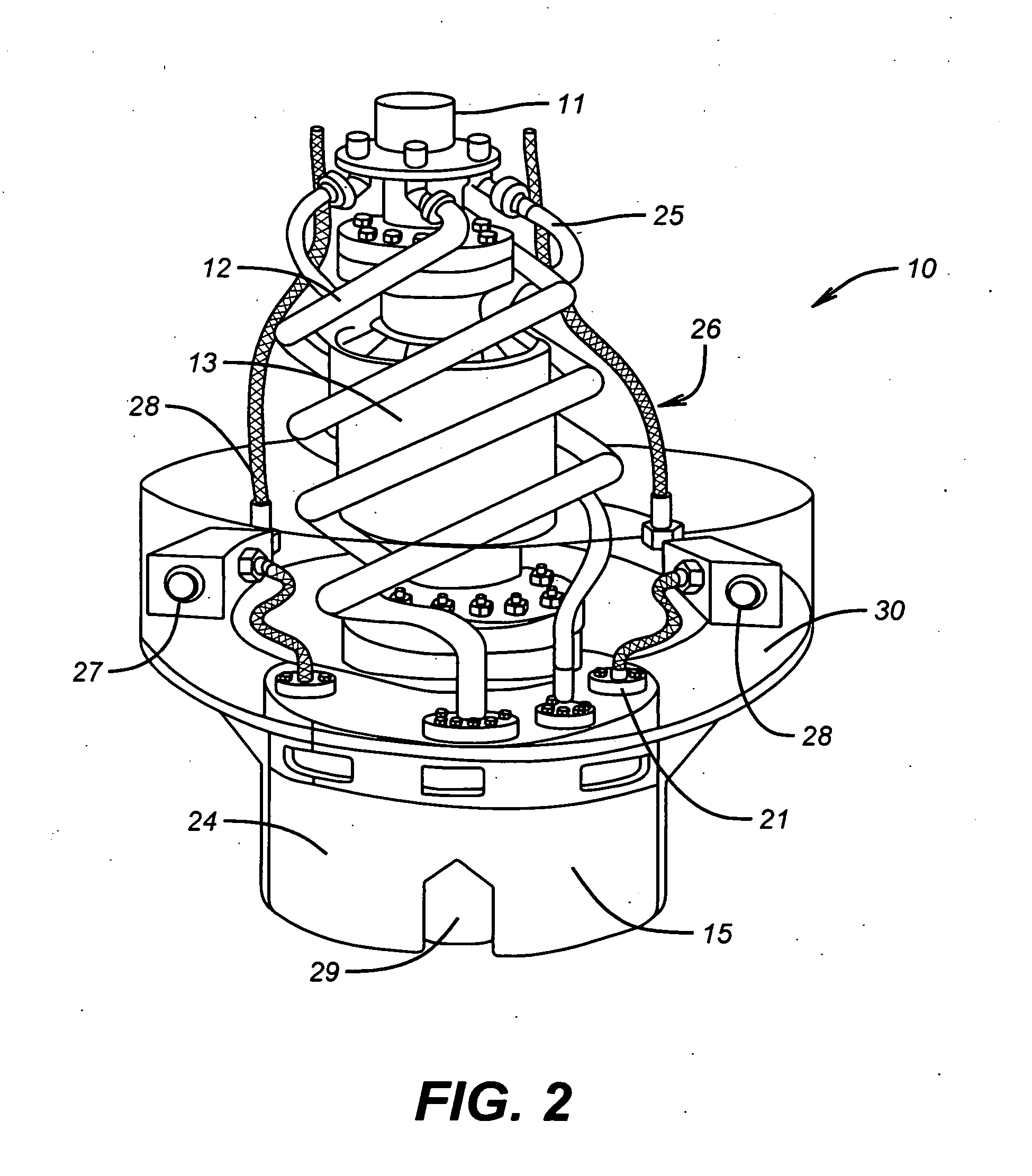
[0026] Referring now to FIG. 1, the present inventions comprise elements that, when assembled and unitized, form a reconfigured subsea Blowout Preventer Stack (BOP Stack) 1 including modular retrievable element control system 200. Variations of the architecture and components of modular retrievable element control system 200 may be utilized subsea, e.g. in production tree, production riser, and subsea manifold control interface applications.

[0027] In a preferred embodiment, BOP Stack 1 comprises riser connector 10, BOP assembly 100, and wellhead connector 50.

[0028] BOP assembly 100 includes control modules 200 that, in a preferred embodiment, are arranged in a vertical array and positioned adjacent to the particular function each control module 200 controls, such as hydraulic functions. Composition of control module 200 sections preferably include materials that are compatible on both the galvanic and galling scales and be suitable for long term immersion in salt water.

[0029] BOP...


PUM


Abstract

A distributed function control module adapted for use in a modular blowout preventer (BOP) stack for use subsea comprises a housing, adapted to be manipulated by a remotely operated vehicle (ROV) with a stab portion adapted to be received into a BOP stack control module receiver. Control electronics, adapted to control a predetermined function with respect to the BOP stack, are disposed within the housing and connected to one or more controllable devices by a wet mateable connector interface.

Description

RELATION TO OTHER APPLICATIONS [0001] This application is a continuation of pending U.S. patent application Ser. No. 11 / 205,893, filed on Aug. 17, 2005, which claims the benefit of U.S. Provisional Application No. 60 / 603,190, filed on Aug. 20, 2004.BACKGROUND OF THE INVENTION [0002] The inventions relate to offshore drilling operations and more specifically to a deepwater subsea blowout preventer stack configuration and its control system architecture, system interface, and operational parameters. [0003] When drilling in deepwater from a floating drilling vessel, a blowout preventer stack (BOP Stack) is typically connected to a wellhead, at the sea floor, and a diverter system, which is mounted under the rig sub-structure at the surface via a marine riser system. Although pressure containing components, connectors, structural members, reentry guidance systems, load bearing components, and control systems have been upgraded for the operational requirement, the overall system architec...

Claims


Application Information

Patent Timeline
Patent Type & Authority Applications(United States)
IPC IPC(8): E21B33/035
CPCE21B33/035E21B33/0355E21B33/064E21B33/038E21B33/0385Y10T137/402Y10T137/8326
Inventor REYNOLDS, GRAEME E.
Owner OCEANEERING INTERNATIONAL
Why Eureka
Try Eureka