Methods and systems for medical imaging

a multi-modality, medical imaging technology, applied in the direction of motor/generator/converter stopper, dynamo-electric converter control, application, etc., can solve the problems of large imaging room, large cost factor for supplying the system and maintaining, and large footprin

Active Publication Date: 2006-09-14
GENERAL ELECTRIC CO
View PDF10 Cites 24 Cited by
  • Summary
  • Abstract
  • Description
  • Claims
  • Application Information

AI Technical Summary

Problems solved by technology

However, having two imaging detector gantries in tandem requires a large footprint and consequently a large imaging room.

Method used


Image

  • Methods and systems for medical imaging
  • Methods and systems for medical imaging
  • Methods and systems for medical imaging

Examples


Embodiment Construction

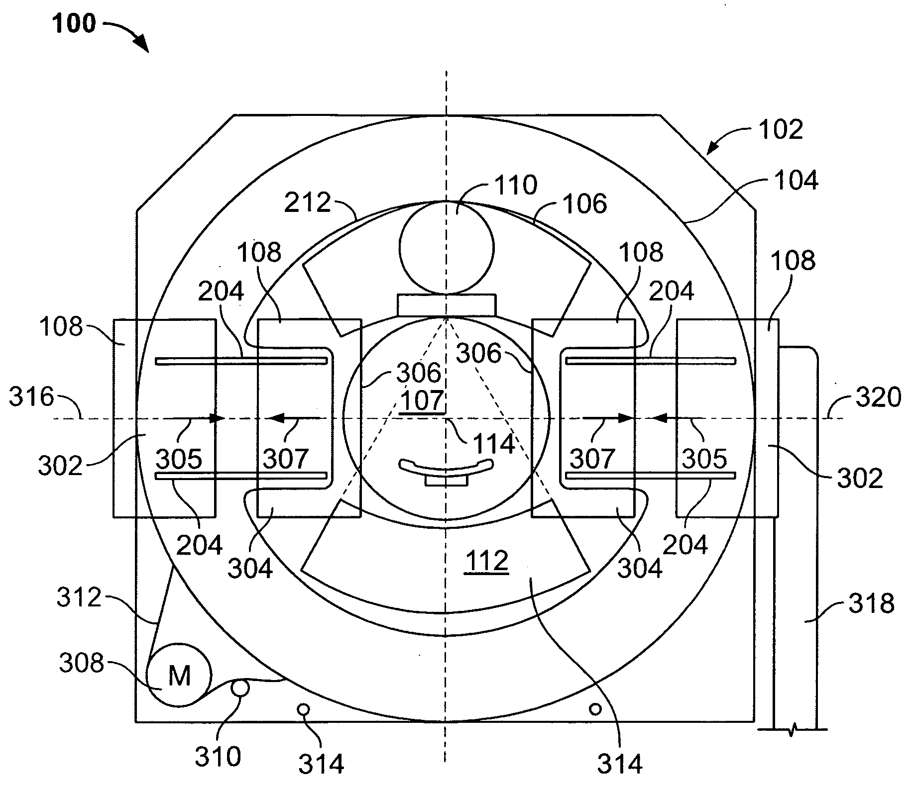
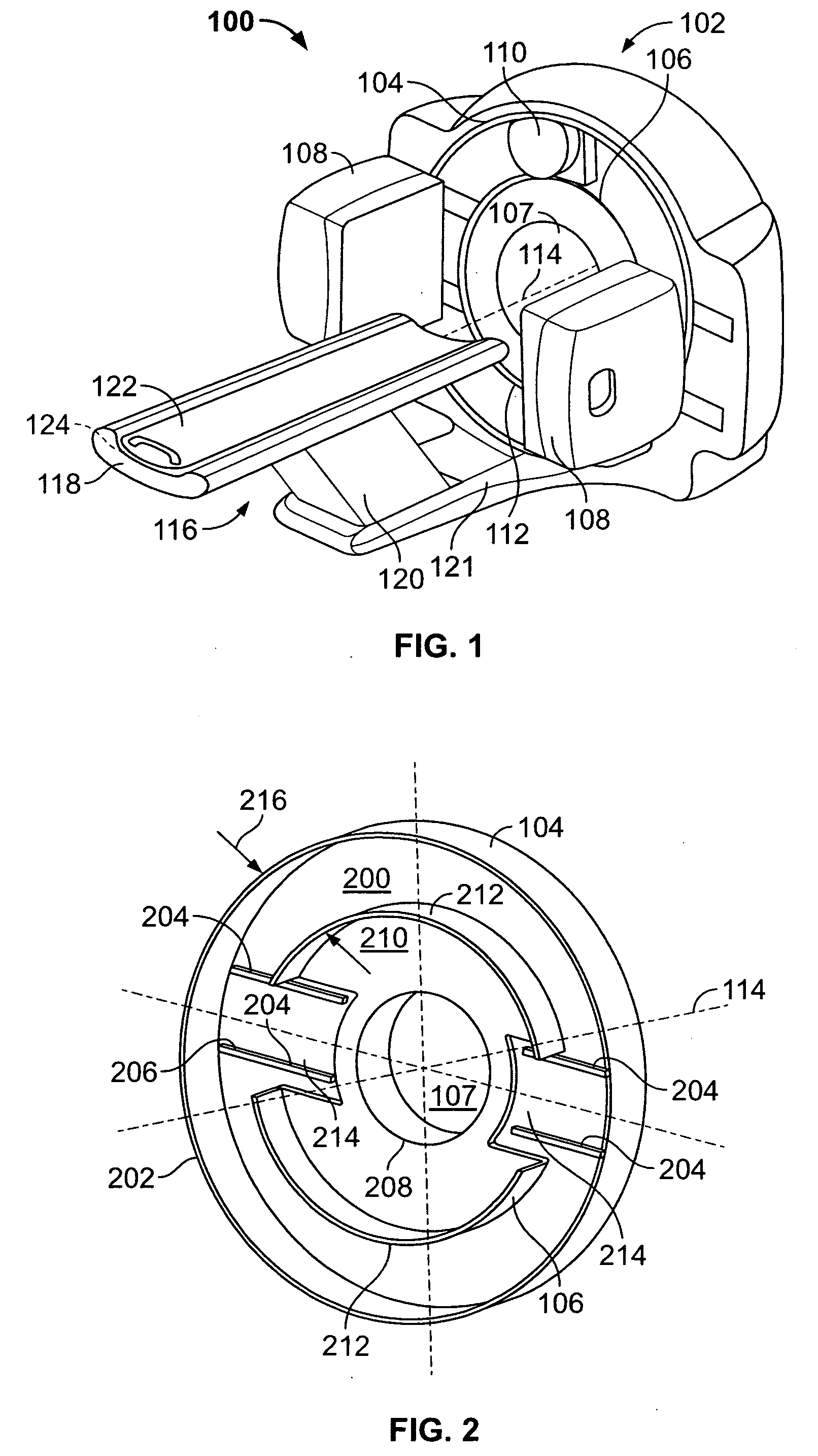
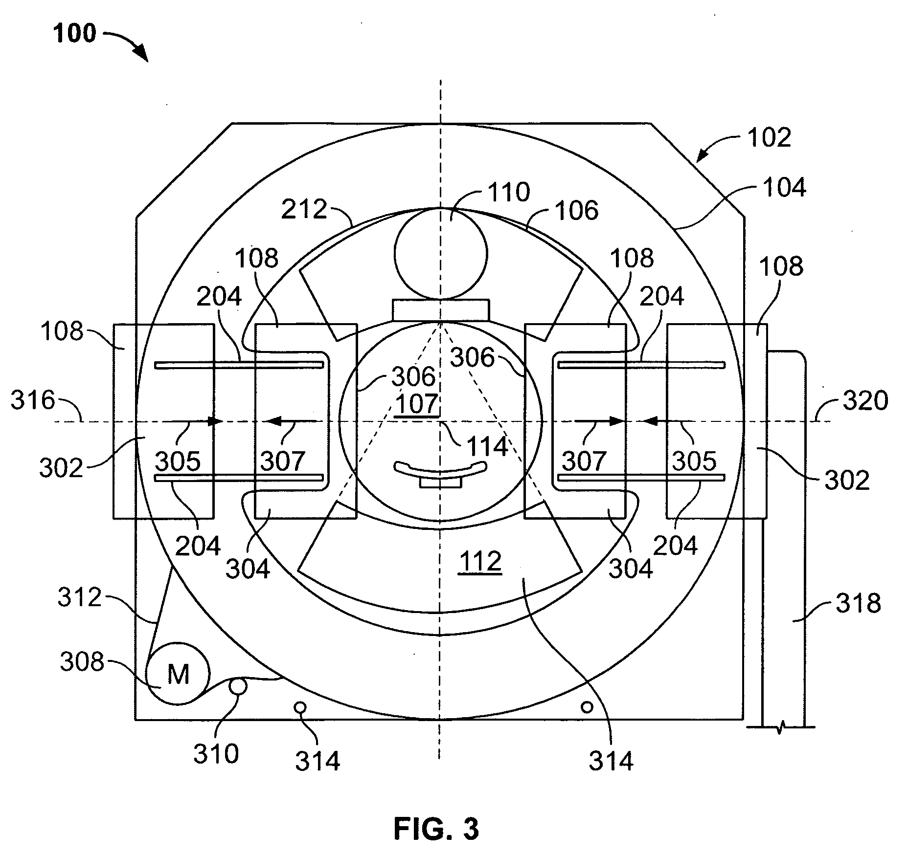
[0015]FIG. 1 is a perspective view of an exemplary embodiment of a multi-modality medical imaging system 100 including an integrated gantry 102 that includes a radially outer rotor 104 and a radially inner rotor 106 concentrically oriented about a gantry central bore 107. Rotor 104 is configured to support one or more nuclear medicine (NM) cameras 108, such as, but not limited to gamma cameras, SPECT detectors, and / or PET detectors. Rotor 106 is configured to support an x-ray source 110 and a substantially diametrically opposed x-ray detector 112. Rotors 104 and 106 are further configured to rotate co-axially about an examination axis 114. A patient table 116 may include a bed 118 slidingly coupled to a bed support system 120, which may be coupled directly to a floor or may be coupled to gantry 102 through a base 121 coupled to gantry 102. Bed 118 may include a stretcher 122 slidingly coupled to an upper surface 124 of bed 118. Patient table 116 is configured to facilitate ingress a...


PUM


Abstract

Methods and systems for medical imaging are provided. The system includes a gantry assembly having a stator, a first rotor rotatably coupled to the stator, the first rotor configured to rotate about an examination axis at a first rotational speed, and a second rotor rotatably coupled to at least one of the stator and the first rotor, the second rotor configured to rotate about the examination axis at the first and a second rotational speed, the second rotational speed being greater than the first rotational speed, the first and second rotors configured to be locked in position with respect to each other during rotation at the first rotational speed, the first rotor configured to be locked in position with respect to the stator during rotation of the second rotor at the second rotational speed.

Description

BACKGROUND OF THE INVENTION [0001] This invention relates generally to medical imaging systems, and more particularly to methods and systems for multi-modality medical imaging. [0002] At least some known multi-modality medical imaging systems use a multi head nuclear medicine (NM) or gamma camera scanner and a computed tomography (CT) or X-ray scanner in tandem. A single patient table may be used to position the patient within each modality scanner without having to readjust the position of the patient on the bed or translate the bed between scanners. Separate gantries are used for each scanner to provide a rotational speed for the NM camera scanner and a different relatively faster rotational speed for the CT scanner. However, having two imaging detector gantries in tandem requires a large footprint and consequently a large imaging room. Using two separate gantries in the imaging system is also a large cost factor for supplying the system and maintaining it. BRIEF DESCRIPTION OF TH...

Claims


Application Information

Patent Timeline
IPC IPC(8): H02P7/06
CPCA61B6/035A61B6/037A61B6/4441
Inventor HAUSNER, DANNYHEFETZ, YARON
Owner GENERAL ELECTRIC CO
Why Eureka
Try Eureka